
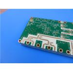
Hybrid PCB RO4350B and TU768 Substrate 10-layer Immersion Gold RF Circuit Board
|


|
This symmetrical hybrid 10-layer RF PCB uses 10mil RO4350B for top and bottom signal layers, paired with Tg170 TU-768 FR4 forming the inner stack. All copper layers use 1oz finished copper, delivering a final laminated thickness of 2.5mm. Green solder mask with white silkscreen is applied to both top and bottom surfaces, alongside immersion gold plating at 140%–150%. The board size is 132mm × 76.5mm including tooling edge, supplied as one piece. Built to IPC 6012D CLASS-3, this PCB features 25μm plated copper inside vias. All through holes are resin plugged and copper plated to fully fill hole cavities.
PCB Specification The table below outlines all key manufacturing parameters for this hybrid PCB.
PCB Stack-up
RO4350B & TU-768 FR4 Laminate Introduction RO4350B is a ceramic-filled hydrocarbon laminate widely used in microwave and RF systems. It maintains low dissipation factor across microwave bands and stable dielectric constant amid temperature variation. The material minimises RF signal attenuation and supports accurate impedance tuning for high-frequency traces. Its thermal expansion behaviour differs noticeably from standard FR4, a key factor to address during hybrid multilayer fabrication.
TU-768 is a high-reliability FR4 with a 170°C glass transition temperature. It provides strong thermal endurance and excellent resistance to CAF formation. The laminate survives multiple lead-free SMT reflow cycles without interlayer separation, while retaining mechanical rigidity for thick multilayer structures. It runs smoothly on standard FR4 production lines and costs much less than ceramic high-frequency laminates.
Applications
Design Rationality of This 10-Layer Hybrid Dielectric Stackup
1. RF Design Value of Dual 10mil RO4350B High-Frequency Substrates on Outer Layers 10mil RO4350B is selected for both top and bottom signal layers. Its low dissipation factor reduces power loss for microwave and RF traces, maintaining consistent impedance for critical RF routing.
The 10mil dielectric thickness creates sufficient space for flexible impedance tuning. Engineers can adjust single-ended or differential line impedance over a wide range to fit different RF transceiver module requirements.
Symmetrical RO4350B placement on the outer layers balances electrical performance on both sides. This matched layout minimises electromagnetic interference across the assembly and avoids uneven field distribution found in asymmetric high-frequency stackups.
2. Cost and Thermal Balance Benefits of Inner Tg170 TU-768 High-Tg FR4 TU-768 replaces RO4350B for all inner layers. RO4350B carries a premium price, so switching inner cores and prepregs to TU-768 cuts raw material costs substantially and makes the 10-layer stack suitable for volume production.
With a Tg rating of 170°C, TU-768 withstands repeated SMT thermal exposure and resists delamination. It solves a common limitation of fully ceramic multilayer boards: poor thermal stability and warpage after thermal cycling.
TU-768 FR4 also delivers high mechanical strength. For this 2.5mm thick 10-layer board, the inner FR4 stack serves as a robust mechanical backbone and improves panel flatness after lamination.
3. Lamination Control Challenges for This 2.5mm Thick 10-Layer Hybrid PCB This 10-layer stack accumulates many copper and dielectric layers to reach a finished thickness of 2.5mm. RO4350B and TU-768 FR4 have mismatched CTE values. During pressing, differing thermal expansion rates build stress at material interfaces. Fabricators must use gradient heating and segmented hold-time lamination profiles to release stress gradually and prevent delamination.
Thick multilayer builds are prone to layer offset and uneven dielectric compression. Precision registration targets and pressure-balanced press plates distribute force evenly over the panel and reduce layer misalignment.
Every laminate and prepreg layer contributes to the final board thickness. Minor thickness deviations of individual sheets stack up across ten layers. Rigorous incoming material checks control thickness tolerance layer by layer, ensuring finished boards consistently hit the target 2.5mm thickness.
|
||||||||||||||||
| Product Tags: 2oz Polyimide FPC Yellow Coverlay FPC |

|
6-layer Hybrid PCB on RO3003 Substrate and 370HR Immersion Gold Circuits Board |

|
Hybrid PCB 4-layer RO4003C and FR4 Material 0.5oz/1oz Copper Green Solder Mask |
|
Hybrid PCB RO4350B and TU768 Substrate 10-layer Immersion Gold RF Circuit Board |

|
RO3003 + Tg170 FR-4 Hybrid 4-Layer PCB Ceramic-Filled PTFE High Frequency Circuit Board |

|
6-Layer RO4350B & IT180A Hybrid PCB 1.6mm Thick Blind Via & Edge Plating High Frequency Board |

|
4-Layer Rogers RT/duroid 6202 Hybrid PCB 1.014mm Gold Plated Circuit Board |