
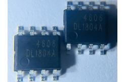
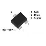
HXY4606 30V Mosfet Power Transistor Complementary MOSFET RDS(ON) < 30m
|
|
HXY4606 30V Complementary MOSFET
Description
The HXY4606 uses advanced trench technologyMOSFETs to provide excellent RDS(ON) and low gatecharge. The complementary MOSFETs may be used toform a level shifted high side switch, and for a host ofother applications.
N-CH Electrical Characteristics (TA=25℃unless otherwise noted)
A. The value of RθJA is measured with the device mounted on 1in2 FR-4 board with 2oz. Copper, in a still air environment with TA =25°C. The value in any given application depends on the user's specific board design. B. The power dissipation PD is based on TJ(MAX)=150°C, using ≤ 10s junction-to-ambient thermal resistance.C. Repetitive rating, pulse width limited by junction temperature TJ(MAX)=150°C. Ratings are based on low frequency and duty cycles to keep initialTJ=25°C. D. The RθJA is the sum of the thermal impedence from junction to lead RθJL and lead to ambient. E. The static characteristics in Figures 1 to 6 are obtained using <300µs pulses, duty cycle 0.5% max. F. These curves are based on the junction-to-ambient thermal impedence which is measured with the device mounted on 1in2 FR-4 board with 2oz. Copper, assuming a maximum junction temperature of TJ(MAX)=150°C. The SOA curve provides a single pulse rating.
N-Channel: TYPICAL ELECTRICAL AND THERMAL CHARACTERISTIC P-Channel Electrical Characteristics (TJ=25°C unless otherwise
noted) A. The value of RθJA is measured with the device mounted on 1in2
FR-4 board with 2oz. Copper, in a still air environment with TA
=25°C. The value in any given application depends on the user's specific board
design. B. The power dissipation PD is based on TJ(MAX)=150°C, using ≤ 10s
junction-to-ambient thermal resistance. C. Repetitive rating, pulse width limited by junction temperature
TJ(MAX)=150°C. Ratings are based on low frequency and duty cycles
to keep initialTJ=25°C. D. The RθJA is the sum of the thermal impedence from junction to
lead RθJL and lead to ambient. E. The static characteristics in Figures 1 to 6 are obtained using
<300µs pulses, duty cycle 0.5% max. F. These curves are based on the junction-to-ambient thermal
impedence which is measured with the device mounted on 1in2 FR-4
board with 2oz. Copper, assuming a maximum junction temperature of
TJ(MAX)=150°C. The SOA curve provides a single pulse rating. THIS PRODUCT HAS BEEN DESIGNED AND QUALIFIED FOR THE CONSUMER
MARKET. APPLICATIONS OR USES AS CRITICALCOMPONENTS IN LIFE SUPPORT
DEVICES OR SYSTEMS ARE NOT AUTHORIZED. AOS DOES NOT ASSUME ANY
LIABILITY ARISINOUT OF SUCH APPLICATIONS OR USES OF ITS PRODUCTS.
AOS RESERVES THE RIGHT TO IMPROVE PRODUCT DESIGN,FUNCTIONS AND
RELIABILITY WITHOUT NOTICE. P-Channel: TYPICAL ELECTRICAL AND THERMAL CHARACTERISTICS |
| Product Tags: n channel mosfet transistor high current mosfet switch |
|
AP2602GY-HF FR4 board 2W 30A SOT-26 IC Voltage Regulator |
|
LED Inductor 0.35W 2.5A Mosfet Power Transistor AP1332GEU-HF |
|
Drive IC AP2308GEN SOT-23 0.69W 3.6A Mosfet Power Transistor |
|
AP2N1K2EN1 IC Chips SOT-723 0.15W 800mA MOSFET Transistor |

|
AP2322GN LOGIC ICS 0.833W 10A MOSFET Power Switch |
|
AP1334GEU-HF 0.35W 8A Mosfet Power Transistor New Condition |