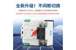
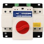
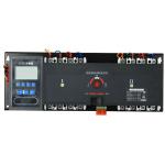
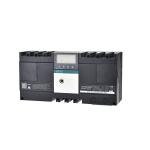
FMQl(PC-grade) -100/2P/3P/4P
(PC-grade) excitation dual power automatic transfer switch
Product Overview
(PC-grade) excitation dual power automatic transfer switch is a
newly developed miniature household power transfer switch. The
switch is mainly used to test whether the main or backup power
supply is normal. When the normal power supply is abnormal, the
standby power supply will start working immediately, thus ensuring
the continuity, reliability and safety of the power supply. It is
designed for use in domestic rail-mounted installations,
specifically in the PZ30 distribution box.
The ATS has solid construction, reliable changeover, easy
installation and maintenance, and long life. ATS is composed of TSE
and controller.
According to GB/T14048.11, Part 6-1: Multifunctional Equipment and
Switchgear, ATS is the most compliant low-voltage switchgear and
control device.
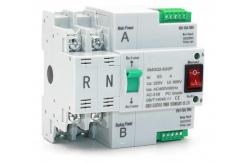
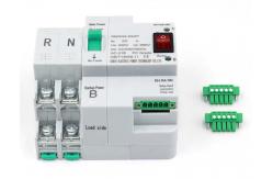
Structural features
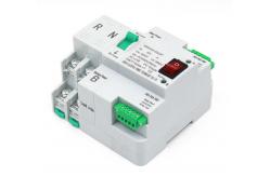
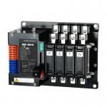
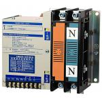
Control device: built-in controller
Product structure: non-stop, rail type, high current, small volume,
two-stage, simple structure, ATS-body Features: fast switching
speed, low failure rate, easy maintenance, reliable performance
Wiring method: wiring in front of the board
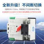
Switching mode: grid to grid, grid to generator, PV to utility,
self-injection and self-recovery
Product shell frame: 100
Product current: 10, 16, 20, 25, 32, 40, 50, 63, 80, 100A
Product classification: direct load type
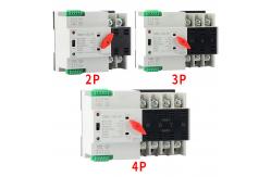
Product pole number: 2, 3, 4
Product standard: GB/T14048.11
ATSE: PC grade
Switching time: 0.008sec/8ms
Uptime and installation conditions
2.1 Ambient air temperature
The maximum temperature should not exceed 40°C, the minimum
temperature should not be lower than -5°C, and the average
temperature should not be higher than 35°C within 24h.
2.2 Altitude
The altitude of the installation site should not be higher than
2000m.
2.3 Atmospheric conditions
When the maximum temperature reaches 40°C, the relative humidity of
the installation site should not exceed 50%; when the temperature
is the minimum temperature -5°C, the relative humidity is higher,
for example: the temperature is 25°C, the relative humidity is 90%.
Due to temperature changes, special measures should be taken to
deal with the occasional condensation on the surface of the
product.
Structural features
Control device: built-in controller
Product structure: non-stop, rail type, high current, small volume,
two-stage, simple structure, ATS-body Features: fast switching
speed, low failure rate, easy maintenance, reliable performance
Wiring method: wiring in front of the board
Switching mode: grid to grid, grid to generator, PV to utility,
self-injection and self-recovery
Product shell frame: 100
Product current: 10, 16, 20, 25, 32, 40, 50, 63, 80, 100A
Product classification: direct load type
Product pole number: 2, 3, 4
Product standard: GB/T14048.11
ATSE: PC grade
Switching time: 0.008sec/8ms
2.4 Pollution level
ATS contamination level is in accordance with GB/T14048.11
designated level 3.
2.5 Installation type
The installation type of ATS is in accordance with the category
specified in GB714048.il.
2.6 Installation conditions
ATS can be installed vertically in the control cabinet or
distribution cabinet. Make sure the installation distance is in
accordance with the requirements.
Precautions
3.1 Manual/Auto Operation
ATS can guarantee the performance of power generation and
disconnection in circuit operation, but for manual operation, due
to the speed of power generation and disconnection or operator
differences. the ATS does not guarantee the above performance.
Excessive silver alloy losses may occur during manual power
generation and disconnection. Therefore, when all power is removed
for inspection and maintenance of the operating system and
contacts, simply pull the selector switch to the manual position.
In general, pull the selector switch to the automatic position.
When operating manually, pull the selector switch to the manual
position. When manual operation is complete, pull the selector
switch from the manual position to the automatic position.
3.2 Control Circuit
The ATS will be active momentarily. After conversion is complete,
the coil in the control circuit will be disconnected by the
internal converter. The coil can operate normally under 80%-110% of
the rated voltage. Too low voltage will cause the coil to heat up
or even spontaneously combust.
| Specification | 100A | | Rated current LE (A) | 16, 20, 25 | 32, 40, 50, 63 | 80, 100 | | Insulation voltage Ui | AC690V.50HZ | | Rated voltage Ue | AC400V,50Hz | | Class | PC grade: can be manufactured and withstood while not generating
short-circuit current | | Use category | AC-33iB | AC-31 B | | Measuring rod | 2P | 3P | 4P | | Weight | 1.7 | 2.1 | 2.6 | | Electrical | Life: 2000 times; manual operation: 5000 times | | Rated short-circuit current lq | 50kA | | Short-circuit protection device(fuse) | RT16-00-63A | | Rated impulse withstand voltage | 8kV | | Control circuit | Rated control voltage Us: AC220V/50HZ Normal operating conditions:
85-110% Us | | Auxiliary circuit | 2 relays, each with two separate sets of contact converter contact
capacity:AC220V/50HzLE=5y | | Contactor changeover time | <50ms | | Operation changeover time | <50ms | | Return switching time | <50ms | | Power off time | <50 ms |
|