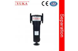
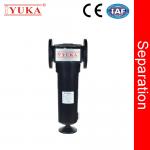
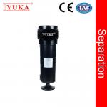
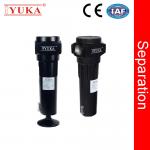
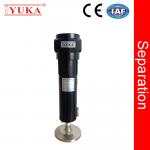
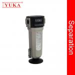
Flange Water Separators
YUKA Filtration offers a range of Compressed Air Water Separators
with proven cyclone technology and ahead-thinking housing design
that drives market leading water removal efficiencies.
Our Compressed Air Water Separators are available in a broad range
of models with connection sizes ranging from 1/2” to DN125”Rc (BSP
Taper).
YUKA Filtration Water Separators have a maximum operating
temperature of 176 ˚F (80˚C), an operating pressure of up to 142.85
psig (10 barg), and flow capacities up to 85 SCFM (144 Nm³/hr) up
to 1766 SCFM (300 Nm³/hr).
Used to remove bulk liquid following the compression of air,
installing a Water Separator reduces the risk of contamination to
production equipment, product spoilage, and costly shutdowns caused
by damage of high levels of moisture and condensate in the system.
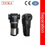
Working Principle
The compressed air gas-water separator is composed of a housing, a
cyclone separator, and sewage components. When the compressed air
containing a large amount of oil and water solid impurities enters
the separator, it spins down along its inner wall. The centrifugal
effect produced causes the liquid water to separate out of the
vapor stream and flow down the wall. Under the action of gravity,
it flows into the separator. The bottom of the device is discharged
by the Automatic Drain Valve.
Feature & Benefit
①99% Separation efficiency from compressed air system
②Zero pressure drop, saving energy and money
③Internal & external anti-corrosion treatment, increase
spanlife and ensure separation efficiency
④With Strong structure, 15 years warranty, reasonable cost
Technical Specification
The flow rate below is the treatment capacity of compressed air
under rated working pressure 7 barg (100psi g). For the application
in other working pressure, please refer to the correction factors.
| Model | Pipe size | Flow rates | Dimension (mm) |
| L/S | m³/min | scfm | W(Width) | D(Depth) | H(Height) |
| WS 15 | RC1/2" | 40.0 | 2.4 | 84.5 | 89 | 79 | 228 |
| WS 25 | RC3/4" | 60.0 | 3.6 | 127.1 | 89 | 79 | 228 |
| WS 50 | RC1" | 75.0 | 4.5 | 158.9 | 89 | 79 | 263 |
| WS 75 | RC1" | 125.0 | 7.5 | 264.8 | 120 | 110 | 335 |
| WS 100 | RC1-1/2" | 166.7 | 10.0 | 353.1 | 120 | 110 | 335 |
| WS 200 | RC2" | 300.1 | 18.0 | 635.6 | 164 | 151 | 564 |
| WS 250 | RC2-1/2" | 416.8 | 25.0 | 882.8 | 164 | 151 | 664 |
| WS 700 | RC2-1/2" | 700.0 | 42.0 | 1483.1 | 200 | 189 | 712 |
| WS 800 | RC3" | 833.5 | 50.0 | 1765.6 | 200 | 189 | 712 |
| WS 800F | DN80/DN100 | 833.5 | 50.0 | 1765.6 | 280 | 189 | 734/744 |
| WS 1000F | DN100/DN125 | 1000.2 | 60.0 | 2118.7 | 280 | 189 | 780/795 |
| WS 1200F | DN100/DN125 | 1166.7 | 70.0 | 2464.0 | 280 | 189 | 1058/1073 |
| Technical requirements | Maximum operating pressure: 10 barg Operating temperature:1.5~ 80°C |
| Pressure | Barg | 1 | 2 | 3 | 4 | 5 | 6 | 7 | 8 | 9 | 10 | 11 | 12 | 13 | 14 | 15 | 16 |
| Psig | 15 | 29 | 44 | 59 | 73 | 87 | 100 | 116 | 131 | 145 | 160 | 174 | 189 | 203 | 219 | 232 |
| Correction factor | 0.38 | 0.53 | 0.65 | 0.76 | 0.85 | 0.93 | 1.00 | 1.07 | 1.13 | 1.19 | 1.23 | 1.31 | 1.36 | 1.41 | 1.46 | 1.51 |
Product Parts
Success Case