
4-Layer Hybrid RO4003C laminate + Dual Tg170 FR4 Prepreg print circuit board (PCB)
|


|
This article presents the design rationale for a 4-layer hybrid dielectric PCB that combines the superior high-frequency performance of Rogers RO4003C™ with the cost-effectiveness and thermal reliability of Tg170 FR4 prepreg. This hybrid construction is engineered for RF/microwave applications requiring controlled impedance, low signal attenuation, and reliable thermal performance in a compact, thin form factor.
By utilizing RO4003C as the RF signal layer and Tg170 FR4 prepreg as the bonding layers, this design achieves an optimal balance of electrical performance, mechanical robustness, and manufacturability.
Rogers RO4003C™ High-Frequency Laminate RO4003C™ is a hydrocarbon ceramic laminate from Rogers Corporation's RO4000® series. It is a proprietary woven-glass-reinforced hydrocarbon/ceramic composite that combines the electrical performance of PTFE/woven-glass materials with the manufacturability of epoxy/glass laminates.
Key Features:
Tg170 FR4 Prepreg Tg170 FR4 prepreg is a high-performance epoxy-based bonding material with a glass transition temperature (Tg) of 170°C. It provides excellent thermal stability, high mechanical strength, and reliable bonding for multilayer PCB applications.
Key Features:
Typical Properties (Tg170 FR4):
Core Value of 8mil RO4003C as the RF Signal Layer Dielectric The 8mil (0.203mm) RO4003C high-frequency laminate serves as the primary RF signal layer dielectric. Its low dielectric constant (Dk 3.38) and low dissipation factor (Df 0.0027 at 10 GHz) are specifically suited for RF transmission lines, significantly reducing high-frequency signal attenuation.
The thin dielectric thickness (8 mil) enables precise impedance control, allowing designers to achieve the exact electrical specifications required for RF circuits. Whether for 50Ω single-ended or differential impedance, the 8mil RO4003C provides a stable, predictable dielectric environment that ensures consistent RF performance across the board.
Cost and Performance Balance with Dual 5mil Tg170 FR4 Prepreg Layers While all-ceramic substrates offer excellent electrical performance, their cost is prohibitively high for many commercial applications. By combining RO4003C with Tg170 FR4 prepreg, this hybrid construction achieves a cost-effective solution without sacrificing critical RF performance.
The Tg170 high-thermal-resistance prepreg provides:
This balanced approach makes the design suitable for high-volume production while maintaining the electrical performance required for RF/microwave applications.
Process Risks from CTE Mismatch in Hybrid Dielectrics The CTE mismatch between RO4003C (Z-axis CTE 46 ppm/°C) and Tg170 FR4 (Z-axis CTE ~45 ppm/°C) requires specialized lamination process control. During the lamination heating and cooling cycles, the differing expansion rates can induce stress at the material interfaces, potentially leading to: Interlayer delamination; Board warpage; Via barrel cracking.
To mitigate these risks, gradient heating and cooling profiles must be carefully designed and strictly controlled. Slow ramp rates in the critical Tg region (150–200°C) and extended dwell times at peak temperature allow stress relaxation and ensure reliable bonding between the RO4003C and FR4 layers.
Design Basis for Achieving 0.556mm Total Laminated Thickness The 0.556mm total laminated thickness is achieved through precise calculation of the constituent material thicknesses:
By fixing the material specifications and strictly controlling thickness tolerances, this stackup achieves a standardized thin-board thickness that meets the design requirements while ensuring manufacturability and repeatability.
PCB Construction Details
PCB Stackup
Typical Applications This 4-layer hybrid PCB is ideal for a wide range of high-performance applications:
Conclusion As a specialized supplier of custom high-frequency circuit boards, we combine the proven performance of Rogers RO4003C (low loss, stable Dk, excellent dimensional stability) and Tg170 FR4 prepreg (high Tg, excellent thermal reliability, cost-effective) with our precision manufacturing capabilities to deliver world-class hybrid PCB solutions.
The 4-layer hybrid offering fully leverages RO4003C's low-loss high-frequency performance and Tg170 FR4's thermal reliability and processing advantages, while incorporating advanced features such as precise impedance control, thin-board construction (0.556mm), and immersion gold finish to ensure optimal signal integrity and reliability.
Whether you are developing RF/microwave modules, antenna systems, or automotive radar modules, our engineering team is ready to support your project. For technical consultations, samples, or volume orders, please contact us today. We look forward to being your trusted partner in high-frequency innovation.
|
||||||||||||||||||||||||||||||||||||||||||||||||||||||||||||||||||||||||||||||||||||||||||||||||||||||||||||||||||||||||||||||||||||||||||||||||||||||||||||||||||||||||||||||||||||||||||||||||||||||||||||||||||||||||||||||
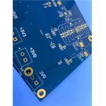
|
6-Layer RO3003+370HR Hybrid PCB with Blind Vias (Layers 1–2) and plugged with conductive copper paste (0.15mm) |

|
8-Layer RO4350B + Isola I-Tera® MT40 multilayer Hybrid RF PCB with blind vias (L1–L2, L7–L8) and 50Ω single-ended impedance control withstand multiple SMT reflow soldering cycles |
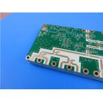
|
10-layer multilayer hybrid RO4350B+Tg170 TU-768 FR4 RF/microwave PCB with Resin-Filled and Plated-Flat Vias |

|
1.1-Meter Extra-Long Rogers RO4003C PCB | 32mil, 1oz Copper, Immersion Gold, No Silkscreen, RF Circuit Board | 1100mm × 350mm |

|
4-Layer Hybrid RO4003C laminate + Dual Tg170 FR4 Prepreg print circuit board (PCB) |

|
Rogers RO3010 DK 10.2 High-Frequency Laminate and Mixed-Material 4-Layer 1.27mm + 0.076mm + 1.27mm PCB for RF Microwave |