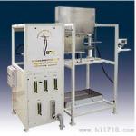
Scope of application: Suitable for fire resistance testing of
building components and the fire resistance performance of
load-bearing vertical partition components.
Working voltage: AC 380V ± 10% 50NZ.
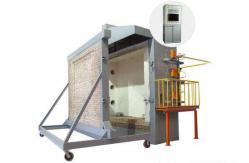
Furnace body: The experimental furnace passage is composed of
bricks, steel structure, and fire insulation materials.
Sample size: 300mm wide × 300mm high (customizable).
The dimensions inside the furnace are approximately:
Vertical furnace: L3.2m×W2.2m×H4.0m
Horizontal furnace: L3.2m×W3.2m×H1.5m.
Gas flow rate: 0-100L/min, with a measurement accuracy of 2.5
levels.
Air flow rate: 0-50m3/min, measurement accuracy≤±0.5m³/min.
Gas tank capacity: ≥ 50kg×6.
Load measurement equipment:±2.5% of the load value should be added
(required for loading type tests).
Test piece gap measurement probe: with a diameter of 6mm±0.1mm and
a diameter of 25mm±0.2mm.
Combustion system: gas distribution system (within 10 meters),
nozzle (not less than 20), and regulating valve.
Combustion gas sources: propane, liquefied gas.
Furnace temperature control system: maximum sampling point of 10
points.
Ventilation system and control air valves, etc.
The measurement range of radiation heat on the back fire surface of
the specimen is 0~10W/cm2.
Furnace pressure measurement range: 0-100pa
Measurement accuracy:≤±3pa.
Test temperature: The furnace temperature control meets the
requirement of T-T0=3451g (8t+1), and its temperature control
deviation
When 0min<t≤10min, d≤15%.
When 10min<t≤30min,d≤10%.
When T>30min, d≤5%.
Furnace temperature:±15℃.
Internal temperature of the specimen:±10℃.
Test piece back fire temperature:±4℃.
Measurement conditions for furnace pressure:
After 5 minutes of the experiment, the furnace should reach the
following specified positive pressure conditions.
Horizontal component - on a horizontal plane 100mm below the bottom
of the test-piece, the furnace pressure is 15pa±5pa.
Vertical component - located at a height of 3m inside the furnace
and 100mm away from the surface of the test-piece. The furnace
pressure is 15pa±5pa.
After 10 minutes of the experiment, the furnace should reach the
following specified positive pressure conditions.
Horizontal component - on a horizontal plane 100mm below the bottom
of the test-piece, the furnace pressure is 17pa±3pa.
Vertical component - located at a height of 3m inside the furnace
and 100mm away from the surface of the test-piece. The furnace
pressure is 17pa±3pa.
Furnace temperature:±15℃, using a thermocouple with a diameter of
1mm.
Test piece back fire temperature:±4℃, with a thermocouple with a
wire diameter of 0.5mm.
Armored platinum rhodium platinum S-value thermocouple, accuracy
level II.
Armored nickel chromium nickel silicon K-value thermocouple, Class
II.
Timing range: 0-120min Timing accuracy: <±1s.
Sample temperature detection system: maximum sampling point of 20
points.
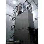
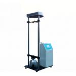
Scope of application: The test furnace meets the technical
indicators and requirements specified in the national standard
GB/T7633-2008, and is suitable for the fire resistance performance
test of non load bearing horizontal doors and rolling shutters.
Main parameters:
Power consumption: 6KW
Furnace pressure measurement range: 0-100Pa Measurement accuracy: ≤
± 3Pa
Air flow rate: 0-50m³/min Measurement accuracy: ≤ ± 0.5 m³/min
Combustion gas source: propane, liquefied gas (user provided)
Gas tank capacity: 50kg × 6
Measurement range of radiation heat on the back fire surface of the
specimen: 0-10W/cm²;
Measurement range of furnace pressure: 15Pa ± 5Pa;
Test temperature: Program temperature rise for 15 minutes, room
temperature~718 ℃,
30min room temperature~821 ℃, 60min room temperature~925 ℃,
90min room temperature~986 ℃; 120min room temperature~1029 ℃;
180min room temperature~1115 ℃, 240min room temperature~1150 ℃;
Temperature measurement sensor: inside the furnace: 9 armored
nickel chromium nickel silicon K-value thermocouples, accuracy
level: II
Backfire: 29 armored nickel chromium nickel silicon K-value
thermocouples, accuracy level: II
Timing range: 0-240min Timing accuracy:<± 1s
External sample size: (special specifications can be customized by
users)
Equipment practical area: long × wide × High (3.8 × 2.4 × 4.5) m;
Equipment weight: 4500 Kg (the test furnace needs to be installed
on site);
Gasification system: 150kg/h (optional).
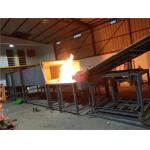
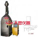
ISO 9705:2003 specifies a testing method for simulating a fire that
occurs in the corner of a small room. This method uses a standard
ignition source and aims to evaluate the impact of surface products
on the development of the fire. The method provides data on the
burning through of a fire that occurs under a standard ignition
source from ignition to burning through; ISO 9705:2003 also
introduces different measurement techniques inside and outside the
room. The ISO 9705 experiment in this article provides background
information and support for potential users. It provides users with
technical information on fire source testing, the heat flux of the
burner in the room, the heat balance of the room in a fire, the
types of smoke and toxic gases produced, and the simulation results
of these tests. It provides users with necessary information to
help them choose test steps for specific projects or regulations.
The testing method in our country adopts this testing method
equivalently, and the developed standards are Appendix B and
Appendix C of GB 20286.
Compliant with standards: ISO 9705, NFPA 266, GB20286 Appendix B
and Appendix C, etc
Technical parameters:
1. 19 inch instrument rack, including oxygen, carbon dioxide, and
carbon monoxide analyzers
2. The oxygen analyzer uses the method of measuring the change in
paramagnetic pressure to detect the oxygen concentration in the
gas. Response time (T90) 3.5 s, internal signal processing
time<1 s, pressure sensor (internal) 50-200 kpa, zero
drift<0.5% of the minimum range on the nameplate/month,
measurement drift<0.5% of the current measurement range/month,
repeatability error<1% of the current measurement range, minimum
detection limit<1% of the current measurement range, linear
error<1% of the current measurement range
3. The carbon dioxide analyzer and carbon monoxide analyzer are non
discrete infrared type, based on the principle that gas molecules
have specific infrared light absorption bands, and adopt a single
beam alternating infrared analysis method. The minimum detection
lower limit is 1% of the current measurement range. When the linear
error measurement is within the maximum range, it is less than±1%
of the full range. The repeatability is less than ± 1% of the
minimum range on the nameplate. The response time (T90 time) is
less than 30 seconds when the sample gas flow rate is approximately
1.2L/min
4. The range of the oxygen analyzer is 0-25%, the range of the
carbon dioxide analyzer is 0-10%, and the range of the carbon
monoxide analyzer is 0-1%
5. Using a temperature controller to control the cold trap, during
the gas extraction process of the experiment, sufficient moisture
is removed
6. Gas sampling dual head pump, capable of transmitting gas samples
generated during combustion to an analyzer approximately 30 meters
away
7. Data collection system (including operation and control
programs)
8. The acquisition board adopts a 16 bit wide gain range, with
analog and digital I/O boards
9. Thermocouple type: K-type, range: ambient temperature~1500
degrees Celsius
10. The data collection system can be started by installing data
recorders or on-site pointers to collect data
11. The data collection system consists of the following
components:
12. Bit thermocouple input module, 16 bit analog input module,
digital input/output module, 12 bit analog output module, 4 and 8
slot baseboards, connection socket, network module, power supply
24V 5A DC universal power input, data acquisition computer,
printer.