1-8 Channels / Bands Hand-pull Box Jammer Defense System , Mobile
Network Jammer Device , Portable Signal Jammer
Product Fetures:
l Using UHF broadband interference technology.
l High effective power (channel power) and large interference radius.
l Imported device, slow start circuit design can avoid the mechanical
switch fire phenomenon, high integration, stable work.
l Perfect self-protection function. When the device is warned of
overheating fault, the shielding device will automatically shut
down the failed module to avoid the damage of the shielding device.
Product Applications:
Prisons, Recording Studios, Banks, Contract Tendering Rooms,
Churches, Classrooms, Testing Facilities, Security Services,
Military Units, Secret Services, News Conference Rooms, Libraries,
Museums, Courts, Border Patrol and Drug Enforcement, Customs, etc.
Product Specification:
| Channel | Working Frequency | Output Power(±3dBm) |
| CH1 | 20-100 MHz | 44.77dBm |
| CH2 | 100-300MHz | 44.77dBm |
| CH3 | 300-500MHz | 47dBm |
| CH4 | 800-1000MHz | 47dBm |
| CH5 | 1520- 1670 MHz | 48.75dBm |
| CH6 | 1800-2000 MHz | 48.75dBm |
| CH7 | 2000-2200 MHz | 48.75dBm |
| CH8 | 2400-2690 MHz | 48.75dBm |
| Power: AC 220V |
Power Consumption : 1000W Mainframe weight: 53.6Kg Size(L×W×H):800×500×310 mm |
| Humidity: 5%-95% Running Temperature: -35 to +80 ℃ |
Product Details:
1.System accessory table
| No | Name | Qty | Unit | Remark |
| 1 | Antenna | 8 | pcs | Omnidirectional |
| 2 | Wire controller | 1 | pcs | |
| 3 | Line controller control line | 1 | pcs | Standard |
| 4 | Spare Line controller control line | 1 | pcs | 20M |
| 5 | Power Line | 1 | pcs | Standard |
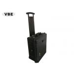
| 6 | Hand-pull Box | 1 | pcs | System Accessary |
2.Omnidirectional Antenna Parameter List
| Input impedence | 50Ω |
| standing wave | ≤1.8 |
| Gain | 3dBi |
| Power Capacity | 150W |
| Direction of Polarization | Vertical Polarization |
Cross Modulation | <-107dBm |
Interface Type | 7/16 or N-K |
Lightning Protection | Direct Grounding |
| Wind Protectionnn | 60(m/s) |
Pole Diameter | Φ25/40(mm) |
3. Product Image
Product Usage:
Step 1 - Open the box
- Open the box. Keep unpacked boxes ready for future removal or
shipment.
- check that the open equipment and accessories are in good
condition. If any defects or damage are found, please contact your
supplier as soon as possible.
Step 2 - Connecting antenna
- Open the suitcase and take out the antenna. Note: do not activate
the shield until the antenna and shield are not well connected,
otherwise, the shield will be severely damaged. All costs and
consequences arising from this will be borne by the user himself.
- Each antenna is connected to the RF output interface of the host
computer one-to-one.
Step 3 - Start Jammer
- Connect the host AC~220V port with the power cord in the suitcase:
then dial the side red knob switch to the "1" file;
- The start and output power adjustment of the wire controller:
1) Connection wire
controller
The 6pin
wire control connection line is connected to the 6pin wire control
connection
port on the
side of the chassis;
2) Control the output and
output power of the power amplifier with a wire controller.
[ALL Ch]:
screen all 4Channel on / off buttons;
[ALL PA]:
power output adjustment keys for all 4Channel of the shield;
[CHX]: the
output of Channel X is the Channel number of 1 ~ 8 when the output
of
Channel X is turned on / off alone;
[PAX]:
regulating the power output of ChannelX alone X is the Channel
number of 1 / 8.
The output power regulation is divided
into five sections: 20: 20 and 40.
Step 4 - Turn off the Jammer
- the power output switch of each channel is closed;
- Power off:
1) Dial the red knob switch on
the side of the chassis to "0";
2) Unplug the power cord;