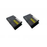
Solar Battery Management System Lithium Ion Rechargeable Lithium Polymer Battery
|
|
Solar Battery Management System Lithium Ion Rechargeable Lithium Polymer Battery
Features: (1) SPI daisy chain structure The BIU and BMU are connected by a daisy-chain topology, and the main board and the slave board can collect data of a total of BIU (16~48)+BMU*n string cells. (2) Single cell voltage collection The BIU and BMU collect the individual cell voltages through a voltage acquisition module. (3) Temperature collection The BIU and BMU collect the temperature of each battery module in the module through the NTC temperature sense. (4) PACK total voltage detection The BIU has a PACK battery pack total voltage detection function. (5) CAN communication function Each BIU has 3 CAN communications. CAN0, used by the BIU to communicate with the CSU and obtain the current total current.
CAN1, used by the BIU to communicate with the charger. CAN2, used by the BIU to communicate with the vehicle VCU/MCU to receive commands and status information of the VCU/MCU. (6) RS485 communication function It can be connected to an external LCD display with 485 bus via 485 bus for power, voltage and current display, and program update is also possible. (7) SOC, SOH, SOP calculation The BIU calculates SOC and SOH, SOP based on parameters such as total current, total voltage, and voltage and temperature of the individual cells. (8) Battery display The BIU calculates the remaining power and displays it on the LCD, vehicle instrumentation, and calibration software. (9) Drive relay / fan The BIU controls the power-up and power-down of the load through the high-side drive. (10) pre-fill module When the BIU controls the load to be powered on, the main circuit load is pre-charged by the pre-charge module, and then power-on after completion. AUX+ can be used as a control for external precharge. (11) Onboard insulation monitoring Real-time monitoring of the high-voltage positive end to the car shell and the high-voltage negative end to the insulation resistance of the car shell, when the threshold is below a certain threshold, an alarm signal is issued. (12) Input signal detection The BIU judges the working state and charging state of the vehicle by detecting the vehicle KeyOn wake-up signal and the charger wake-up signal. (13) Key information is saved after power down When the BMS detects that the system is powered down, it stores the key data of the system, such as the highest and lowest voltages and corresponding positions, SOC, current, and historical faults, in the FLASH of the MCU for storage.
Applications: new energy vehicles, electric vehicles, golf carts, sightseeing cars, sweepers, power
|
|||||||||||||||||||||||||||
| Product Tags: li ion battery management system lithium ion battery monitoring system | |||||||||||||||||||||||||||

|
High Voltage BMS Battery Management System For Electric Vehicles / Golf Carts |

|
Customized Li Ion Battery Management System Protection Circuit Control |

|
12 Volt BMS Battery Management System Integrated Balancing Bms Battery |

|
Sightseeing Cars BMS Battery Management System Overcurrent Protection |

|
Solar Battery Management System Lithium Ion Rechargeable Lithium Polymer Battery |

|
Energy Saving BMS Battery Management System For Lithium Ion Batteries |

