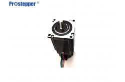
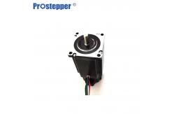
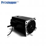
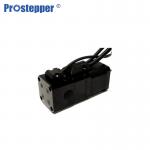
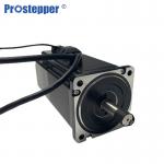
2.2N.M NEMA24 Brake Stepper Motor 1.8 Degree
Bipolar motors
Bipolar motors have a single winding per phase. The current in a winding needs to
be reversed in order to reverse a magnetic pole, so the driving
circuit must be more complicated, typically with an H-bridge arrangement (however there are several off-the-shelf driver chips available
to make this a simple affair). There are two leads per phase, none
is common.
A typical driving pattern for a two coil bipolar stepper motor
would be: A+ B+ A− B−. I.e. drive coil A with positive current,
then remove current from coil A; then drive coil B with positive
current, then remove current from coil B; then drive coil A with
negative current (flipping polarity by switching the wires e.g.
with an H bridge), then remove current from coil A; then drive coil
B with negative current (again flipping polarity same as coil A);
the cycle is complete and begins anew.
Static friction effects using an H-bridge have been observed with
certain drive topologies.
Dithering the stepper signal at a higher frequency than the motor
can respond to will reduce this "static friction" effect.
Product description
Automatic assembly line
Automatic assembly line, improve production efficiency, low cost
without human operation, one line down intelligent mechanical
automatic assembly
Strictly control the production of parts to improve the quality of
parts
Automatic machine operation, stable automatic work, high processing
efficiency.
Longer Life
Stepping motor is a mechanical structure,which does not need be
changed by electric brush or Hall sensor,thus reducing the
probability and increasing the motor life.Stepping motor life
usually determined by the life of the bearing.
Specifications
| Model | PST60H268-4L40M | PST60H286-4L50M |
| Holding Torque | 2.2N.m | 3.2N.m |
| Related Current | 4A/Phase | 5A/Phase |
| Resistance | 0.5Ω/Phase | 0.4Ω/Phase |
| Inductance | 1.2MH/Phase | 2MH/Phase |
| Inertia | 340g.cm² | 690g.cm² |
| Black Torque | 1.3N.m | 1.3N.m |
Radial Load&Axial Load
| Motor Size | Shaft Diameter (mm) | Radial Load (N) | Axial Load (N) |
| Distance from Mounting Surface (mm) |
| 5 | 10 | 15 | 20 | 25 | 30 | 35 |
| NEMA8 | 4 | 15 | 12 | | | — | | | 3 |
| NEMA 11 | 5 | 50 | 35 | 25 | | — | | | 5 |
| NEMA 14 | 5 | 50 | 35 | 25 | 20 | — | — | — | 10 |
| NEMA 17 | 5 | 50 | 35 | 25 | 20 | — | — | | 15 |
| NEMA 23 | 8 | 270 | 180 | 130 | 100 | 90 | | — | 20 |
| NEMA 24 | 8 | 200 | 135 | 100 | 82 | 58 | — | — | 30 |
| NEMA 34 | 14 | 620 | 550 | 480 | 390 | 340 | 290 | 260 | 60 |
Speed/Torque Characteristics(Reference Value)
Applications of Stepper Motors
s
Computer controlled stepper motors are a type of motion-control
positioning system. They are typically digitally controlled as part
of an open loop system for use in holding or positioning
applications.
In the field of lasers and optics they are frequently used in
precision positioning equipment such as linear actuators, linear
stages, rotation stages, goniometers, and mirror mounts. Other uses
are in packaging machinery, and positioning of valve pilot stages
for fluid control systems.
Commercially, stepper motors are used in floppy disk drives,
flatbed scanners, computer printers, plotters, slot machines, image
scanners, compact disc drives, intelligent lighting, camera lenses,
CNC machines and, more recently, in 3D printers.