
Speed Pulse Signal Output 12-36v Dc Brushless Motor Driver Board Controller
|
Detailed Product Description
|
24VDC 3-phase BLDC motor PWM speed driver for sensorless BLDC motor
JYQD-V6.3E2
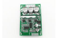
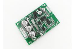
Driver board diagram
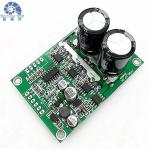
Driver board diagram with heatsink Wiring diagram 5V -----Driver board internal output voltage Signal ---- Motor speed pulse signal output port, 5V pulse signal. 1. Control port Z/F---- Rotating direction control ports. Connect “5V” high level or
no connect is Forward direction, connect 0 V low level or connect
to GND is reverse direction. VR ----Speed control port. Analog voltage linear speed regulation
0.1v -5V, The input resistance is 20K Ohm ,connect with GND when
input PWM speed regulation, PWM frequency:1-20KHZ; Duty cycle
0-100% GND—Used for Drive board internal control 2. Power port MA ----motor phase A MB ---- motor phase B MC---- motor phase C GND----DC- VCC----DC + 3. Use shielded wires if the drivers board has more than 50 cm
distance from the motor, otherwise it may lead to abnormal driving,
affecting the normal use. 4.Control port distance: 2.54mm,Power port distance:3.96 mm 5. Pay attention to the insulation between the driver MOSFET and
the heatsink or the installation plate. Dimensional drawing DOWNLOAD JYQD-V6.3E2 USER MANUAL |
|||||||||||||||||||||
| Product Tags: 12 36v Dc Brushless Motor Driver Board Dc Brushless Motor Driver Board Controller 12 36v driver bldc |
Related Products

|
OWP Series Automotive Electronic Pump For Truck Engine Cooling System 24VDC Input Pump Head 2.5 Bar |

|
JUYI 24V BLDC Motor Driver Board For Power Tool And Household Electrics |

|
High Efficiency 36VDC Motor Driver Board For Curtain Machine |

|
JYQD 12V-36V DC BLDC Motor Driver Board For Hall Sensor Motor |
|
JYQD-V7.5E 36V-72V BLDC Motor Driver For Hall Sensor Motor PWM Speed Regulation. |

|
Bextreme Shell PWM Speed Control Motor Driver Board 12-36V 500W For BLDC Motor. |
Email to this supplier