
Rectangle Brushless DC Motor Driver Speed Pulse Signal Output Bare Board
|
Detailed Product Description
|
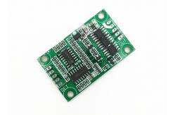
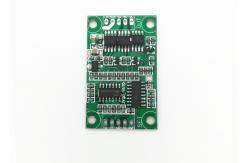
12V-24VDC 3A small size JYQD-V6.7 BLDC motor driver for sensorless
BLDC motor (For Brushless Sensorless DC motor )
Application notes: 1. Confirm that the voltage and power parameters of the motor not
exceed the range of the driver board as specified. 2. This BLDC motor driver board is used for 3-phase brushless
sensorless motor, but not suit for all 3-phase brushless sensorless
motors directly. If the driving effect is not good (such as
starting jitter, reversing, the motor noload working current is too
large, the speed is not stable, the efficiency is low, and can’t
start-up with load.) Customers can adjust the resistance and
capacitance of the driver board according to the actual situation
to achieve the best driving effect (see the attachment for how to
do the adjustment) 3. JYQD-V6.7 driver board is bare board without housing and
heatsink. If the power of the motor below 60W ,it does not need to
add heatsink, It only needs to ensure normal ventilation and well
insulation. If the power of the motor more than 36W, it must add
heatsink like the diagram as below. 4. Please take note that JYQD-V6.7 driver board has no anti-reverse
connection protection, it will permanently damage the driver board
if reversed polarity connection. 5. The 5V output port on the driver board prohibits connect
external device. It is only applicable to the external
potentiometer and switch of the board for speed regulation and
reversal. 6. The “SC” terminal on the JYQD-V6.7 driver board is the motor
speed pulse output signal (push-pull output), and the maximum
output current is less than 5mA. Driver board diagram Wiring diagram 5V -----Driver board internal output voltage SC ---- Motor speed pulse signal output port, 5V pulse signal. 1. Control port Z/F---- Rotating direction control ports. Connect “5V” high level or
no connect is Forward direction, connect 0 V low level or connect
to GND is reverse direction. VR ----Speed control port. Analog voltage linear speed regulation
0.1v -5V, The input resistance is 20K Ohm ,connect with GND when
input PWM speed regulation, PWM frequency:1-20KHZ; Duty cycle
0-100% GND—Used for Drive board internal control 2. Power port MA ----motor phase A MB ---- motor phase B MC---- motor phase C GND----DC- VCC----DC + 3. Use shielded wires if the drivers board has more than 50 cm
distance from the motor, otherwise it may lead to abnormal driving,
affecting the normal use. 4.Control port distance: 2.54mm,Power port distance:2.54 mm 5. Pay attention to the insulation between the driver MOSFET and
the heatsink or the installation plate. Dimensional drawing DOWNLOAD JYQD-V6.7 USER MANUAL
|
||||||||||||||||
| Product Tags: bldc motor driver 3 phase motor driver |
Related Products

|
OWP Series Automotive Electronic Pump For Truck Engine Cooling System 24VDC Input Pump Head 2.5 Bar |

|
JUYI 24V BLDC Motor Driver Board For Power Tool And Household Electrics |

|
High Efficiency 36VDC Motor Driver Board For Curtain Machine |

|
JYQD 12V-36V DC BLDC Motor Driver Board For Hall Sensor Motor |
|
JYQD-V7.5E 36V-72V BLDC Motor Driver For Hall Sensor Motor PWM Speed Regulation. |

|
Bextreme Shell PWM Speed Control Motor Driver Board 12-36V 500W For BLDC Motor. |
Email to this supplier