
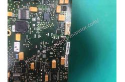
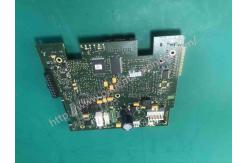
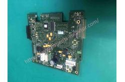
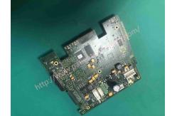
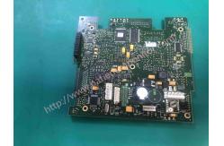
P/N 453564055981 VM6 Patient Monitor Parts Mainboard Motherboard
|
|
P/N 453564055981 PHiliphhilip VM6 Patient Monitor Mainboard Motherboard New Version
Main PCB
The main PCB contains these components: • Intel X_Scale µProcessor – 32 Mb flash memory – 64 Mb SDRAM • LAN controller – 10/100T • Power management control – Voltage regulator – Smart battery charger that monitors status of battery • USB – 1.1 compliant • LCD drivers • Front end interface circuitry • Fan control • LVDS buffer for LCD interface • Power distribution and monitoring • VGA DAC • Audio • NBP pump control circuitry • Connectors – etCO2 (wire to etCO2) – DC input (wire to AC/DC module) – Speaker – LCD – LCD backlight – Control board – B2B: patient daughter board – B2B: VGA daughter board – B2B: I/O daughter board – B2B: recorder board
Removing the Main PCB
Cautions After replacing the main PCB, you must reset the monitor serial number, reconfigure the system, and recalibrate the monitor
1.Separate the front and rear monitor case assemblies
2.Remove the main board assembly.
3.Remove the front end assembly
NOTE - Before reassembling the monitor, please note the calibration values. These values are needed to reset the serial number and calibrate the monitor
4.Remove the five Torx T10 screws from the main board. 5.Disconnect all of the connectors and NBP tubes from the main board
6.Remove the main board from the assembly
7.If the version of the motherboard you are installing does not require the LCD adapter board, remove the adapter board from the LCD frame and connect the LCD directly to the motherboard.
8.After replacing the motherboard and reassembling the monitor, you must do Follow the procedure below before use: • "Reset Serial Number" • "Set System Configuration" • "Calibrate IBP (SureSigns VM6 and VM8 SE)" • "Calibrate SureSigns VM6 and VM8 SE Temperature"
Reinstalling the Main Board Assembly
1.Slide the board assembly into the rear case (guiding the power cord retaining clip through the rear cover) and ensuring enough clearance for the speaker and fan cables.
2.Push the assembly until it snaps into place in the case. 3.Replace the four Torx T10 screws and washers on the bottom of the rear case to ensure that the main board assembly is aligned correctly in the case.
Main Board Versions Depending on the version of the motherboard in the monitor, the LCD may require a breakout board. Use the image below to determine the board version. If the board has a connector in the area shown below, an adapter board must be installed. If there are two connectors in this area, you don't need a breakout board and you can connect the LCD cable directly to the motherboard.
|
||||||||||||
| Product Tags: 453564055981 Patient Monitor Parts Motherboard Patient Monitor Parts |
|
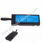
Mindray Patient Monitor Battery LI13I001A Suit For Ipm5 Ipm8 Ipm10 Ipm12 IMEC5 IMEC8 IMEC10 IMEC12 New |
|
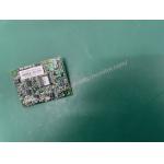
051-000943-00 Patient Monitor Spo2 Board Mindray T1 IPM12 IPM10 IPM8 Imec8 Imec10 Imec12 |
|
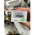
Patient Monitor Printer Recorder TR60-F Mindray IMEC7 IMEC8 IMEC10 IMEC12 IPM8 IPM9 IPM10 IPM12 MEC T5 T6 T8 Series |
|
PHiliph MX400 MX450 MX Series Patient Monitor AC/DC IV2-FLEX ASSY-PWR AC / DC Power Supply 453564281221 |
|
P/N 453564271711 PHiliph MX400 Mx450 MX Series Patient Monitor Mainboard |
|
MX450 Patient Monitor Battery Board Power Supply Hospital Equipment |