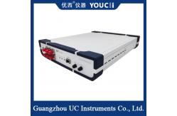
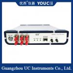
100Gbps Multi-Frequency Division Clock Recovery Instrument
U9764A CDR (Clock Recovery Module ) is mainly used to
provide clock recovery signal in the test environment without
triggering clock, so as to use the sampling oscilloscope to test
the optical eye diagram of the device. The typical application is
the testing of optical network equipment or the BOB prodUt in PON
application. Because the photometric device itself has no frequency
division clock output, it is necessary to recover the clock signal
to trigger the sampling oscilloscope when testing the optical eye
diagram.
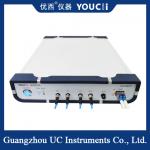
U9764A CDR has a SFP28 optical port, which is suitable
for SFP encapsulated conventional SFP28, SR,LR,BIDI and other
optical modules. It only needs the receiving end of the optical
module to convert the optical signal to the electrical signal, and
then extract and output the clock of the electrical signal. Clock
signal is mainly used for the trigger signal of oscilloscope.
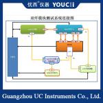
The full name of CDR is Clock and Data Recovery. As the name
suggests, the main functions of CDR are:
1) to provide the clock signal for each circuit at the receiver
end.
2) to judge the received signal, to facilitate the recovery and
subsequent processing of the data signal.
| NO. | Technical indicators | Max | Min | unit |
| 1 | Data rate range | 28.1 | 25.6 | Gbps |
| 2 | Wavelength range | 1600 | 800 | nm |
| 3 | Optical input range (determined by module sensitivity) | +3 | -12 | dBm |
| 4 | Clock recovery output frequency division ratio | 2 / 4 / 8 / 16 / 64 / 256 |
|
| 5 | Output electrical clock amplitude | 800(typical value) | mVpp |
| 6 | CML clock differential output swing | 800 | 200 | mVpp |
| 7 | The clock output jitter randomly | 800 | 300 | fs |
| 8 | Clock frequency (28.1Gbps as an example) | 14.05 | 0.11 | GHz |
| 9 | Internal Signal Loss Detection (LOS) | 128 (over duty) | 5(sensitivity) | mV |
| 10 | Power supply voltage (external power input voltage) | 5.5 | 4 | V |
| 11 | Operating temperature | 70 | 10 | ℃ |
| 12 | Adaptive module type | SFP28,SR,LR,BIDI |
|