1. Sample limitation | This test chamber prohibits:
Testing or storage of flammable, explosive, and volatile substance
samples
Testing or storage of samples of corrosive substances
Testing or storage of biological samples
Testing or storage of strong electromagnetic emission source
samples
Testing or storage of radioactive material samples
Test or storage of highly toxic substance samples
Testing or storage of samples that may produce flammable,
explosive, volatile, highly toxic, corrosive and radioactive
materials during testing or storage |
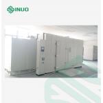
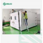
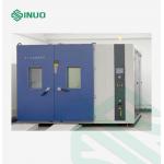
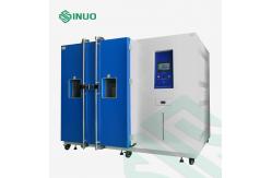
2. Volume, size and weight |
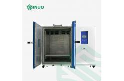
2.1 Nominal content volume | 2880L |
2.2 Inner chamber size | W 2400×D 800×H 1500 (mm) |
2.3 External dimensions | Approx. W3100×D1320×H2100 (mm) |
2.4 Weight | Approx. (1500) KG |
3. Performance |
3.1 Temperature range | -40 ℃~+85℃ (C type) Air-cooled type |
3.2 Humidity range | (30 ~ 95)% RH (refer to temperature and humidity controllable range chart, no
active wet and heat load) Temperature and humidity controllable range chart |
3.3 Temperature fluctuation | ≤0.5℃ (The temperature fluctuation is half of the difference
between the measured maximum temperature and the minimum
temperature at the center point) |
3.4 Temperature uniformity | ≤2.0℃ (Temperature uniformity is the arithmetic mean of the
difference between the highest and lowest temperature measured in
each test) |
3.5 Humidity deviation | ≤ 2%R.h (>75%), 3%R.h. (<75%) |
3.6 Heating time | RT~ 100℃ (2℃-3℃)/min |
3.7 Cooling time | RT~ -40℃(0.7℃-1℃)/min |
3.8 Working noise | 80dB(A) (1m in front of the gate, 1.2m above the ground, in free
space) |
4. Structural characteristics |
4.1 Overall structure | 1. Integral, modular design 2. The equipment is divided into the following parts: cabinet part,
air circulation part, refrigeration part, heating system,
humidification system, electrical control part |
4.2 Thermal insulation structure | Outer wall material: double-sided galvanized steel, surface spray
treatment or Q235 steel, surface pickling, phosphating, surface
spray treatment Inner wall material: SUS304 stainless steel plate
Insulation material: special composite with special heat insulation
performance insulation material: rigid polyurethane board and glass
wool |
4.3 Standard configuration of test chamber | Power cord (3 meters) 1pc (also can be adjusted according to user
site conditions)
Over temperature protector 1pc
Lead hole (ф100) 1pc (placed on the left side of the equipment,
equipped with stainless steel cover) |
4.4 Load bearing | The load-bearing capacity of the sample rack is not less than
30KG/layer Load-bearing capacity of the bottom plate of the test chamber:
≥100Kg/m2 (uniform load) |
4.5 Observation window | One piece of window is placed on the gate, the size of the
observation window is: height 480mm×width 350mm, the heating wire
of the observation window is automatically turned on during the low
temperature test to prevent condensation and frost, to ensure the
test situation inside the chamber can be observed through the
observation window |
4.6 Lighting | The door of the chamber is equipped with a moisture-proof LED
lighting lamp, which is convenient for observing the test samples
in the chamber. The lighting is controlled by a switch on the
control panel outside the chamber |
4.7 Control operation interface | Touch control screen, main power switch, buttons, over-temperature
protector, etc. |
4.8 Machinery room | Refrigeration unit, power distribution control cabinet, exhaust
fan, etc. |
4.9 Power distribution control cabinet | Cooling fan
Switchboard |
5. Air circulation part |
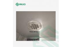
5.1 Fan | The fan stirs the air heated by the heater in the chamber, and then
sends the air out the channel, allowing the air to circulate in the
chamber |
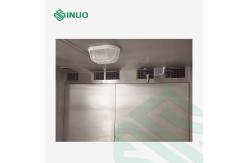
5.2 Wind tunnel | Including air outlet and air return with air guide, to achieve
efficient heat exchange for the equipment |
5.3 Heater | Nickel-chromium alloy electric heating wire heater
Heater control mode: non-contact and other periodic pulse width
adjustment, SSR (solid state relay)
The main heating source of the equipment provides the required heat
for heating and constant temperature of the equipment, with
reasonable surface heating load, no open flame, long life |
5.4 Humidifier | Boiler heating and humidification method
Stainless steel armored heater
Heater control mode: non-contact and other periodic pulse width
adjustment, SSR (solid state relay)
Water level control device, heater anti-dry burning device |
6. Refrigeration system |
| The refrigeration part is the main part of the equipment that
generates the cold source, which provides the required cold energy
for the equipment's cooling, low temperature, and constant
temperature. According to the different test conditions of the
equipment, the refrigeration system is automatically turned on.
Provide cooling capacity for the corresponding test process, so as
to achieve the purpose of meeting the performance indicators of the
equipment |
| 6.1 Compressor | Adopt imported France Tecumseh air-cooled compressor, the
refrigeration system of this equipment adopts cascade refrigeration
system |
| 6.2 Heat Exchanger | Finned heat exchanger is used to provide cooling and refrigerant
for the refrigeration system to provide cold and heat exchange
places |
| 6.3 Evaporator | The main cold source in the chamber, it is the main component for
energy exchange between the cold capacity of the refrigeration unit
and the hot air in the chamber |
| 6.4 Throttling device | Combination of expansion valve and capillary tube, combination
control, as the throttling device of this equipment, allows the
state of the refrigerant to be changed after passing through this
device |
| 6.5 Refrigerant | R404A/R23 (Ozone depletion index is 0) |
| 6.6 Components Brand |
|
7. Control System |
7.1 ontroller | 7 inch color touch screen temperature controller, Chinese and
English display |
7.2 Operation mode | Fixed value/program mode: users can perform programming test and
constant test according to test requirements and needs |
7.3 Setting method | Set on the touch screen |
7.4 Input | Thermal resistance signal |
7.5 Output | Multi-point temperature and humidity signal output |
7.6 Control method | Control and adjust the temperature and humidity in the test
chamber, and automatically determine the working status of each
executive elements (such as compressor, fan, heater, water circuit,
etc.)
PID action and automatic calculation function
Ratio band (PB): 0.1%~999.9%
Integration time (IT): SR-92/SR-93 1~3600 seconds
Differential time (DT): SR-92/SR-93 1~1200 seconds |
7.7 Setting range | Temperature: -100~+300℃, humidity: 0~100%RH |
7.8 Control precision | Temperature: 0.1°C, humidity: 0.1%RH, time 0.1 minutes |
7.9 Test data display | Can display set temperature, set relative humidity, measured
temperature, measured relative humidity, total running time,
remaining time of section, heating and humidification status,
calendar time, etc. |
7.10 Ancillary functions | Alarm display function, prompting the cause of failure, power
failure protection function, upper and lower temperature and
humidity alarm function, timing function (automatic start and
automatic stop), self-diagnosis function |
Measuring sensor | Armored platinum resistance high-precision temperature sensor |
7.11 Power failure protection | In the user setting interface, there is a prompt to set whether the
equipment will continue to operate after a power outage. The user
can set according to needs, including the maximum allowable time
interval after a power outage |
8. Other configurations |
8.1 Total power leakage circuit breaker | Schneider, AC380V, 60Hz, three-phase four-wire + protective ground |
| 8.2 Safety protection device | The equipment has multiple alarm protection functions such as
over-temperature, fan over-heating, over-current, compressor
over-pressure, over-heating, etc. The fault self-diagnosis function
of the controller can ensure that once the equipment is abnormal,
it will cut off the power of the main components and send out an
alarm at the same time. Including: (1) Air switch (to prevent overcurrent and short circuit);
(2) Fan overheating protection (protect the blower and prevent the
fan from overheating);
(3) Compressor overpressure, overheating and overcurrent protection
(protect the compressor to prevent excessive pressure, temperature
and current);
(4) Over-temperature protection (to prevent the test room
temperature from being too high and protect the sample); (5) Local temperature protection in the air-conditioning room (to
prevent the temperature around the heating part from being too
high, and to protect the shell of the test room);
(6) Dry-burning protector for thermal fuse wire (to prevent the
boiler from burning out of water);
(7) Fuse (to prevent short circuit of control circuit and lighting
circuit);
(8) Tank pressure protection (to prevent damage to the laboratory
body caused by excessive pressure in the tank) |
8.3 Others | Over temperature alarm in the chamber
Fan overheating alarm
Compressor overpressure and overheating alarm
Total power phase sequence and phase loss protection
Leakage Protection |
8.4 Power Cable | One five-wire (four-core cable + protective grounding wire) cable
(length can be determined according to customer requirements) |
9. Conditions of use | The following conditions are guaranteed by the user |
9.1 The installation site | 1. The ground is level and well ventilated
2.No strong vibration around the equipment
3.No strong electromagnetic field around the equipment
4.No flammable, explosive, corrosive substances and dust around the
equipment 5. Ground bearing capacity of the site: not less than 800kg/m2
6. Appropriate use and maintenance space is left around the
equipment, as shown below:
A:≥10cm B:≥30cm C:≥120cm D: ≥10cm E:≥40com |
9.2 Environmental conditions | 1. Temperature: 5 ℃ ~ 35 ℃
2. Relative humidity: ≤85%
3. Air pressure: 86kPa ~ 106kPa |
9.3 Tap water (Only for damp heat equipment with pure water machine) | Flow ≥200kg / h, pressure 0.1MPa ~ 0.25MPa
Tap water meets GB 5749-1985 standard for sanitary drinking water
Note: DN15 female thread connector for pure water machine (The pure water machine should be prepared by user) |
| 9.4 Power supply conditions | AC380V three-phase four-wire + protective ground wire
Allowable voltage fluctuation range: (1±10%) 380V
Allowable frequency fluctuation range: (1±1%) 60Hz
The grounding resistance of the protective earth wire is less than
4Ω; TN-S power supply or TT power supply
The user is required to configure an air or power switch of the
corresponding capacity for the equipment at the installation site,
and this switch must be independent and dedicated for the use of
this equipment
About 15.8 kW |
| 9.5 Others | Opening the door of the test chamber during the test will cause
temperature and humidity fluctuations in the chamber; if the door
is opened multiple times or is left open for a long time or the
test sample emits moisture during the test, the refrigeration
system heat exchanger may freeze and does not work. |
