|
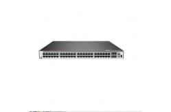
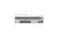
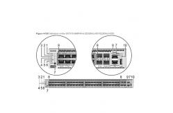
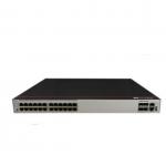
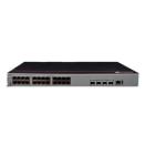
Price - Huawei S5700 Series SwitchesForty-Eight PoE+ 10/100/1000BASE-T Ports Four 10GE SFP S5731S-S48P4X-A (02353AJJ/02353AJJ-001/02353AJJ-003) Version Mapping Table 4-1349 lists the mapping between the S5731S-S48P4X-A chassis and software versions. Table 4-1349 Version mapping | Series | Model | Software Version | | S5731S-S | S5731S-S48P4X-A | 02353AJJ: V200R019C00 and later versions 02353AJJ-001: V200R020C10 and later versions 02353AJJ-003: V200R021C10SPC600 and later versions (If V200R021C10SPC500 is used, install V200R021HP0121 or a later patch.) | Appearance and Structure Figure 4-527 S5731S-S48P4X-A (02353AJJ) appearance Figure 4-528 S5731S-S48P4X-A (02353AJJ-001/02353AJJ-003) appearance | 1 | Forty-eight PoE+ 10/100/1000BASE-T ports | 2 | Four 10GE SFP+ ports Applicable modules and cables: | | 3 | One console port | 4 | One ETH management port | | 5 | One USB port | 6 | One PNP button NOTICE: To restore the factory settings and reset the switch, hold down the button for at least 6 seconds. To reset the switch, press the button. Resetting the switch will cause service interruption. Exercise caution when you press the PNP button. | | 7 | Ground screw | 8 | Fan module slot 1 | | 9 | Fan module slot 2 | 10 | Power module slot 1 | | 11 | Power module slot 2 | - | - | Port Description 10/100/1000BASE-T port A 10/100/1000BASE-T Ethernet electrical port sends and receives service data at 10/100/1000 Mbit/s, and must use an Ethernet cable. Table 4-1350 describes the attributes of a 10/100/1000BASE-T Ethernet electrical port. Table 4-1350 Attributes of a 10/100/1000BASE-T Ethernet electrical port | Attribute | Description | | Connector type | RJ45 | | Standards compliance | IEEE802.3, IEEE802.3u, IEEE802.3ab | | Working mode | 10/100/1000 Mbit/s auto-sensing | | Maximum transmission distance | 100 m | 10GE SFP+ optical port A 10GE SFP+ Ethernet optical port supports auto-sensing to 1000 Mbit/s. It sends and receives service data at 1000 Mbit/s or 10 Gbit/s. Table 4-1351 describes the attributes of a 10GE SFP+ Ethernet optical port. Table 4-1351 Attributes of a 10GE SFP+ port | Attribute | Description | | Connector type | LC/PC | | Optical port attributes | Depend on the optical module used | | Standards compliance | IEEE802.3ae | | Working mode | GE/10GE auto-sensing | Console port The console port is connected to a console for on-site configuration. The port must use a console cable. The console port is used when a switch is powered on for the first time. For details about the attributes of a console port, see Table 4-1352. Table 4-1352 Attributes of a console port | Attribute | Description | | Connector type | RJ45 | | Standards compliance | RS-232 | | Working mode | Duplex Universal Asynchronous Receiver/Transmitter (UART) | | Baud rate | 9600 bit/s, 19200 bit/s, 38400 bit/s, 57600 bit/s, or 115200 bit/s Default value: 9600 bit/s | ETH management port You can connect a switch to a configuration terminal or network management workstation through the ETH management port to configure the switch locally or remotely. The port must use an Ethernet cable. You can choose to download the software package through the ETH management port in the BootLoad menu. File transfer through the ETH management port is faster than transfer through the console port. Table 4-1353 describes the attributes of an ETH management port. Table 4-1353 Attributes of an ETH management port | Attribute | Description | | Connector type | RJ45 | | Standards compliance | IEEE802.3 | | Working Mode | 10/100 Mbit/s auto-sensing | | Maximum transmission distance | 100 m | In V200R012C00 and later versions, you can log in to the switch that contains the ETH management port for the first time through the ETH port. For details, see "First Login to a Switch" in the Configuration Guide - Basic Configuration. If you have logged in to the switch for the first time by pressing and holding the MODE button for 6 seconds or longer and saved the configuration, the default configuration on the ETH port will be cleared. In this case, you cannot log in to the switch for the first time through the ETH port. You are advised to log in to the switch for the first time through the ETH port. USB port The USB port can have a USB flash drive connected to upgrade the switch, or transfer configuration files or other files. The USB port can only connect to a USB flash drive that complies with USB 2.0. USB flash drives from different vendors differ in model compatibility and drivers. If a USB flash drive cannot be used, try to replace it with another one from a mainstream vendor. Switches support a maximum of 128 GB USB flash drives. Indicator Description Hold down the mode switch button for 6s and release it to start the web initial login mode. Either of the following situations will occur: - If the switch has no configuration file, the system attempts to enter the web initial login mode. In this mode, the status of mode indicators is as follows:
- If the system enters the web initial login mode successfully, all mode indicators turn green and stay on for a maximum of 10 minutes.
- If the system fails to enter the initial login mode, all mode indicators fast blink for 10 seconds and then restore the default status.
- If the switch has a configuration file, the system cannot enter the web initial login mode. In this case, all mode indicators fast blink for 10s, and then return to the default states.
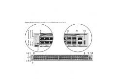
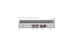
Figure 4-529 Indicators on the S5731S-S48P4X-A (02353AJJ) Figure 4-530 Indicators on the S5731S-S48P4X-A (02353AJJ-001/02353AJJ-003) Table 4-1354 Description of indicators on the switch | No. | Indicator | Name | Color | Status | Description | | 1 | PWR1 | Power module indicator | - | Off | No power module is available in power module slot 1, or the switch has only one power module but the power module does not work normally. | | Green | Steady on | A power module is installed in power module slot 1 and is working normally. | | Yellow | Steady on | The switch has two power modules installed. Any of the following situations occurs in power module slot 1: | | 2 | PWR2 | Power module indicator | - | Off | No power module is available in power module slot 2, or the switch has only one power module but the power module does not work normally. | | Green | Steady on | A power module is installed in power module slot 2 and is working normally. | | Yellow | Steady on | The switch has two power modules installed. Any of the following situations occurs in power module slot 2: | | 3 | SYS | System status indicator | - | Off | The system is not running. | | Green | Fast blinking | The system is starting. | | Green | Steady on | During the system startup preparation phase, the SYS indicator is steady green, which lasts for a maximum of 30 seconds. | | Green | Slow blinking | The system is running normally. | | Red | Steady on | The system does not work normally after registration, or a fan alarm or a temperature alarm has been generated. | | 4 | MST | Stack indicator | - | Off | - If you are not changing the indicator mode (default): The switch is a standby or slave switch in a stack or the stacking function is not enabled on the switch.
- If you are changing the indicator mode: The stack mode is not selected.
| | Green | Steady on | The stack mode is selected. The switch is a standby or slave switch in a stack, and the service port indicators show the stack ID of the switch. | | Green | Blinking | - If you are not changing the indicator mode (default): The switch is the master switch in a stack or a standalone switch with the stacking function enabled.
- If you are changing the indicator mode: The stack mode is selected. The switch is the master switch in a stack or a standalone switch, and the service port indicators show the stack ID of the master switch. After 45 seconds, the service port indicators automatically restore to the status mode.
| | 5 | SPEED | Speed indicator | - | Off | The speed mode is not selected. | | Green | Steady on | The speed mode is selected, and service port indicators show the speed of each port. | | 6 | PoE | PoE indicator | - | Off | The PoE mode is not selected. | | Green | Steady on | The PoE mode is selected, and service port indicators show the PoE status of each port. | | 7 | MODE | Mode switch button | - | - | - When you press this button once, the service port indicators change to the stack mode and show the stack ID of the local switch.
- When you press this button a second time, the service port indicators change to the speed mode and show the speed of each service port.
- When you press this button a third time, the service port indicators change to the PoE mode and show the PoE status of each service port.
- When you press this button a fourth time, the service port indicators restore to the default mode and show the connection status and link activity of each service port.
If you do not press the MODE button within 45 seconds, the service port indicators restore to the default mode. In this case, the SPEED and PoE indicators are off. | | ID | ID indicator NOTE: The mode switch button on the 02353AJJ has an ID indicator. | - | Off | The ID indicator is not used (default state). | | Blue | Steady on | The indicator identifies the switch to maintain. The ID indicator can be turned on or off remotely to help field engineers find the switch to maintain. | | 8 | - | Service port indicator | Meanings of service port indicators vary in different modes. For details, see Table 4-1355 and Table 4-1356. | | 9 | ETH | ETH port indicator | - | Off | The ETH port is not connected. | | Green | Steady on | The ETH port is connected. | | Green | Blinking | The ETH port is sending or receiving data. | | 10 | - | USB-based deployment indicator | - | Off | - No USB flash drive is connected to the switch.
- The USB port is damaged.
- The indicator is damaged.
- The USB flash drive does not have any configuration file and cannot be used for deployment.
- The switch has been upgraded using the USB flash drive and is restarting.
| | Green | Steady on | A USB-based deployment has been completed. | | Green | Blinking | The system is reading data from a USB flash drive. | | Yellow | Steady on | The switch has copied all the required files and completed the file check. The USB flash drive can be removed from the switch. | | Red | Blinking | An error has occurred when the system is executing the configuration file or reading data from the USB flash drive. | Table 4-1355 Description of service port indicators in different modes (one indicator for each port) | Display Mode | Color | Status | Description | | Default mode | - | Off | The port is not connected or has been shut down. | | Green | Steady on | A link has been established on the port. | | Green | Blinking | The port is sending or receiving data. | | MST stack mode | Green | Off | Port indicators do not show the stack ID of the switch. | | Steady on | The switch is not the master switch in a stack. -
If the indicator of a port is steady on, the number of this port is the stack ID of the switch. -
If the indicators of ports 1 to 9 are steady on, the stack ID of the switch is 0. | | Blinking | The switch is the master switch in a stack. -
If the indicator of a port is blinking, the number of this port is the stack ID of the switch. -
If the indicators of ports 1 to 9 are blinking, the stack ID of the switch is 0. | | Speed mode | - | Off | The port is not connected or has been shut down. | | Green | Steady on | 10M/100M/1000M port: The port is operating at 10 Mbit/s or 100 Mbit/s. | | Green | Blinking | 10M/100M/1000M port: The port is operating at 1000 Mbit/s. | | PoE mode | - | Off | The port is not providing power to a powered device (PD). | | Green | Steady on | The port is providing power to a PD. | | Green | Blinking | The power of the PD connected to the port exceeds the power capacity of the port or the power threshold configured on the port. Alternatively, the PD does not comply with IEEE standards. | Table 4-1356 Description of service port indicators in different modes (two indicators for each port) | Display Mode | Color | Status | Description | | Default mode | - | Off | The port is not connected or has been shut down. | | Green | Steady on | A link has been established on the port. | | Yellow | Blinking | The port is sending or receiving data. | | Speed mode | - | Off | The port is not connected or has been shut down. | | Green and yellow | Steady on | 1000M/10GE port: The port is operating at 1000 Mbit/s. | | Green and yellow | Blinking | 1000M/10GE port: The port is operating at 10 Gbit/s. 1000M port: The port is operating at 1000 Mbit/s. | Power Supply Configuration The switch is a PoE switch and supports two power module slots, each of which can have a 1000 W PoE or 600 W PoE power module installed. Pluggable AC and DC PoE power modules can be used together in the same switch. Table 4-1357 Power supply configurations | Power Module 1 | Power Module 2 | Available PoE Power | Maximum Number of Ports (Fully Loaded) | | 1000 W AC (220 V) 1000 W DC | – | 760 W | - 802.3af (15.4 W per port): 48
- 802.3at (30 W per port): 25
| | 1000 W AC (110 V) | – | 665 W | - 802.3af (15.4 W per port): 43
- 802.3at (30 W per port): 22
| | 1000 W AC (220 V) 1000 W DC | 1000 W AC (220 V) 1000 W DC | 1600 W | - 802.3af (15.4 W per port): 48
- 802.3at (30 W per port): 48
| | 1000 W AC (110 V) 1000 W DC | 1000 W AC (110 V) | Versions earlier than V200R021C10: 1330 W V200R021C10 and later versions: 1520 W | - 802.3af (15.4 W per port): 48
- 802.3at (30 W per port): 48
| | 600 W AC (220 V) | – | 380 W | - 802.3af (15.4 W per port): 24
- 802.3at (30 W per port): 12
| | 600 W AC (110 V) | – | 95 W | - 802.3af (15.4 W per port): 6
- 802.3at (30 W per port): 3
| | 600 W AC (220 V) | 600 W AC (220 V) | 950 W | - 802.3af (15.4 W per port): 48
- 802.3at (30 W per port): 31
| | 600 W AC (110 V) | 600 W AC (110 V) | 380 W | - 802.3af (15.4 W per port): 24
- 802.3at (30 W per port): 12
| | 1000 W AC (220 V) 1000 W DC | 600 W AC (220 V) | 1330 W | - 802.3af (15.4 W per port): 48
- 802.3at (30 W per port): 44
| When a switch has two power modules installed, the two power modules work in redundancy mode to provide power for the chassis and in load balancing mode to provide power for PDs. Heat Dissipation The S5731S-S48P4X-A uses pluggable fan modules for forced air cooling. Air flows in from the front side and exhausts from the rear panel. This figure only shows the airflow direction and does not depict the actual device. Technical Specifications Table 4-1358 lists technical specifications of the S5731S-S48P4X-A. Table 4-1358 Technical specifications | Item | Description | | Memory (RAM) | 2 GB | | Flash | 1 GB in total. To view the available flash memory size, run the display version command. | | Mean time between failures (MTBF) | 54.96 years | | Mean time to repair (MTTR) | 2 hours | | Availability | > 0.99999 | | Service port surge protection | Common mode: ±6 kV | | Power supply surge protection | - Using AC power modules: ±6 kV in differential mode, ±6 kV in common mode
- Using DC power modules: ±2 kV in differential mode, ±4 kV in common mode
| | Dimensions (H x W x D) | - Basic dimensions (excluding the parts protruding from the body): 43.6 mm x 442.0 mm x 420.0 mm (1.72 in. x 17.4 in. x 16.5 in.)
- Maximum dimensions (the depth is the distance from ports on the front panel to the handle on the rear panel): 43.6 mm x 442.0 mm x 448.0 mm (1.72 in. x 17.4 in. x 17.7 in.)
| | Weight (with packaging) | 9.9 kg (21.83 lb) | | Stack ports | 10GE SFP+ ports on the front panel | | RTC | Supported | | RPS | Not supported | | PoE | Supported | | Rated voltage range | - AC input: 100 V AC to 130 V AC, 200 V AC to 240 V AC, 50/60 Hz
- High-Voltage DC input: 240 V DC
- DC input: -48 V DC to -60 V DC
| | Maximum voltage range | - AC input: 90 V AC to 290 V AC, 45 Hz to 65 Hz
- High-Voltage DC input: 190 V DC to 290 V DC
- DC input: -38.4 V DC to -72 V DC
| | Maximum power consumption (100% throughput, full speed of fans) | - Not providing the PoE function: 132 W
- 100% PoE loads: 1750 W (PoE: 1440 W)
| | Typical power consumption (30% of traffic load, tested according to ATIS standard) | 108 W | | Operating temperature | -5°C to +45°C (23°F to 113°F) at an altitude of 0-1800 m (0-5906 ft.) NOTE: When the altitude is 1800-5000 m (5906-16404 ft.), the highest operating temperature reduces by 1°C (1.8°F) every time the altitude increases by 220 m (722 ft.). The switch cannot be started when the ambient temperature is lower than 0°C (32°F). | | Storage temperature | -40°C to +70°C (-40°F to +158°F) | | Noise under normal temperature (27°C, sound power) | < 62.3 dB(A) | | Relative humidity | 5% to 95%, noncondensing | | Operating altitude | 0-5000 m (0-16404 ft.) | | Certification | - EMC certification
- Safety certification
- Manufacturing certification
| | Part number | 02353AJJ 02353AJJ-001 02353AJJ-00 | Notices:
1. Open the packaging, check the products carefully, and take them gently.
2. The product is a brand new original unopened equipment.
3. All products 3 year warranty, and the buyer is responsible for the return shipping cost.
International Buyers Please Note:
Import duties, taxes, and charges are not included in the item price or shipping cost. These charges are the buyer's responsibility.
Please check with your country's customs office to determine what these additional costs will be prior to bidding or buying.
Customs fees are normally charged by the shipping company or collected when you pick the item up. These fees are not additional shipping charges.
We won't under-value merchandise or mark the item as a gift on customs forms. Doing that is against U.S. and international laws.
Customs delays are not the responsibility of the seller.
Inspur NF5270M6/NF5280M5/ NF2180M3/NP5570M5/NF3120M5/NF8480M5
Dell P5820/T7920/R250/R450/R540/R650/R650xs/R740/R750/R750xs
xfusion 2288HV5 2488HV5 5588HV5
Need to contact:
WeChat: +8613651169867
Skype: +8613651169867
WhatsApp: +8615732685076
|