
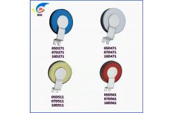
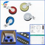
05D High-Energy Chip Varistor 05D271 05D471 05D511 For Instruments
|
|
1 Application areas 1.1 LED, DOB LED 1.2 Electrical instruments 1.3 Security equipment 1.4 Communication equipment 1.5 Home appliances
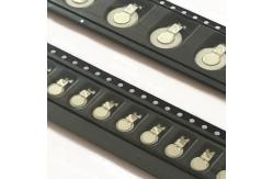
2 product features 2.1 Meet RoHS requirements 2.2 SMD packaging, convenient for automation 2.3 Use saves labor and has high cost performance 2.4 Using high-energy pressure-sensitive chips, it has high energy absorption density and good pulse performance. 2.5 Performance remains stable for a long time 2.6 Wide operating temperature range: -40℃~125℃ 2.7 Safety certification: UL/cUL, TUV, CQC
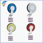
4 Product Identification:LK
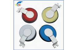
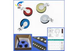
5.1 Product size and appearance(unit:mm)
5.2 Pad size design recommendations
6 Main electrical properties
7 Reliability
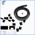
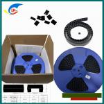
8 Pulse resistance performance test method 8.1 Maximum inrush current (8/20μs lightning wave) Experimental method: Extract two groups of 10 chip varistors each from the batch number, and test the varistor voltage and leakage current parameters. One group is applied with a peak current I1 lightning pulse once, and the other group is applied with a peak current I2 lightning pulse twice ( interval of 60 seconds), and test the pressure-sensitive parameters of the sample after cooling. After the test, the sample is required to have no visible damage on its appearance, a varistor voltage change rate of ≤10%, a leakage current of ≤30μA after the test, and a nonlinear coefficient of ≥20. 8.2 Maximum flow capacity (8/20 -1.2/50μs combined wave) Experimental method: Extract 10 chip varistors from the batch number, test the varistor parameters, apply combined wave pulses with the open-circuit voltage and short-circuit current peaks respectively being the maximum current capacity voltage/current values 40 times (the interval between two times is 60 seconds, changing the direction of the pulse signal every 5 times), and test the pressure-sensitive parameters of the sample after cooling. After the test, the sample is required to have no visible damage on its appearance, a varistor voltage change rate of ≤10%, a post-test leakage current of ≤50μA, and a nonlinear coefficient of ≥20. 9 Packing 9.1 Tape packaging size (unit:mm)
9.1.2 7D series
9.1.3 10D series
9.2 Packing quantity
10 Precautions 10.1 Conventional ■ LKVDRH is suitable for LED lights, electrical instruments, security equipment, communication equipment, home appliances and other products. Considering product applicability and reliability, it should not be used in other aspects unless permitted by the company during the design stage. ■ In order to ensure the reliability of chip varistor in actual use, extreme working conditions should be taken into consideration during the design stage and a certain margin should be left. ■ To avoid arcing, the edge of the varistor chip should be at least 2.5mm away from other conductive components. If space permits, the larger the distance, the better. ■ In order to improve product safety and reliability, it is recommended that the circular electrode of the chip body be used as the L line and the square hardware terminal be used as the N line when designing the pad. ■ To reduce the chance of damage to the silicon bridge, it is not recommended to install the varistor in a rectified DC circuit. 10.2 Usage environment ■ Ambient temperature: -40-125℃ ■ Relative humidity: ≤95% ■ Atmospheric pressure: 86-106Kpa ■ Vibration frequency: 10-50Hz ■ Acceleration: 98m/S²
10.3 Storage ■ Should be stored in the original packaging of the varistor and do not open the packaging for storage; ■ Original packaging storage conditions: storage temperature -25 °C to +45 °C, average annual relative humidity ≤75%, maximum not exceeding 95%; ■ For chip varistors, contamination of the varistor surface during storage, handling and processing should be avoided; ■ Varistors should avoid being stored in other harmful environments that may affect their performance; ■ Please use the varistor within 6 months after receiving the goods. 10.4 Transport ■ The varistor should avoid falling and collision during transportation; ■ It is recommended to wear gloves when handling varistor; ■ For chip type varistor, contamination of the silver surface of the varistor should be avoided during transportation. 10.5 Welding (where applicable) ■ It is recommended to use medium and low temperature solder paste as soldering material; ■ Insufficient preheating may cause cracks in the varistor ceramic chip; ■ The recommended welding temperature is 255±5℃. Excessive welding temperature may cause the varistor electrode to corrode silver; ■ Rapid cooling by immersion in solvent is not advisable; ■ It is recommended to completely remove the flux after soldering.
roduct Description
Features:
Technical Parameters:
Applications:Lin Kun SMD Varistor is a surface mount varistor device, which is widely used in various applications. It is a surface mounted varistor component with high-quality and reliable performance. The brand name Lin Kun is UL, VDE, and CSA certified and has a minimum order quantity of 4000/3000/2000pcs/plate. This SMD varistor has a peak current of 20-1200 (A) for 8/20μs and a maximum clamping voltage of 24-175 (V) for 8/20μs. Its part number is QV0402~2220H Series and the maximum working voltage is DV: 5.5V-85V and AC: 4V-60V, and the varistor voltage @1mA DC is 12V-102V. The price of the SMD Varistor is negotiable and it has a fast delivery time of 5-7 days. The payment terms are T/T, Paypal, and Western Union. The supply ability of the SMD Varistor is 1000000PCS/Month. Customization:Lin Kun SMD Surface Mount Varistors Brand Name: Lin Kun Highlights
Support and Services:SMD Varistor Technical Support and Service Packing and Shipping:SMD Varistor Packaging and Shipping: FAQ:SMD VaristorBrand Name: Lin Kun Questions & AnswersQ1: What is SMD Varistor? Q2: What are the application of SMD Varistor? Q3: What is the Brand Name of SMD Varistor? Q4: What certifications do SMD Varistors have? Q5: What is the minimum order quantity for SMD Varistors?
|
|||||||||||||||||||||||||||||||||||||||||||||||||||||||||||||||||||||||||||||||||||||||||||||||||||||||||||||||||||||||||||||||||||||||||||||||||||||||||||||||||||||||||||||||||||||||||||||||||||||||||||||||||||||||||||||||||||||||||||||||||||||||||||||||||||||||||||||||||||||||||||||||||||||||||||||||||||||||||||||||||||||||||||||||||||||||||||||||||||||||||||||||||||||||||||||||||||||||||||||||||||||||||||||||||||||||||||||||||||||||||||||||||||||||||||||||||||||||||||||||||||||||||||||||||||||||||||||||||||||||||||||||||||||||||||||||||||||||||||||||||
| Product Tags: high-energy chip varistor 05D 271 high-energy chip varistor For Instruments 510v SMD Chip Varistor | |||||||||||||||||||||||||||||||||||||||||||||||||||||||||||||||||||||||||||||||||||||||||||||||||||||||||||||||||||||||||||||||||||||||||||||||||||||||||||||||||||||||||||||||||||||||||||||||||||||||||||||||||||||||||||||||||||||||||||||||||||||||||||||||||||||||||||||||||||||||||||||||||||||||||||||||||||||||||||||||||||||||||||||||||||||||||||||||||||||||||||||||||||||||||||||||||||||||||||||||||||||||||||||||||||||||||||||||||||||||||||||||||||||||||||||||||||||||||||||||||||||||||||||||||||||||||||||||||||||||||||||||||||||||||||||||||||||||||||||||||

|
10D High Energy Chip Varistors 10D271 471 511 561 621 Automatically And For LED |
|
07D High-Energy Chip Varistors 471 511 561 621 Series 175-385V 2KV/1KA |
|
05D High-Energy Chip Varistor 05D271 05D471 05D511 For Instruments |
|
3225 SMD Zinc Oxide Varistor Voltage 3225K201-3225K681 For High Surge Current Suppression |
|
4032 Zinc Oxide SMD Varistor 4032K201-4032K681 For High Surge Current |

|
QV0806P431KT101 SMD Chip Varistor Small High Sensitivity For Power Line Protection |