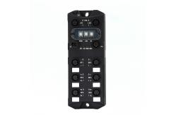
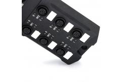
RFID Gateway Module EtherCat Industrial Communication 18-30V M12
Connector
1. Advantages: 1>. High protection level and strong corrosion resistance, can
be used in harsh industrial environments 2>. Supports mainstream PLCs , provides mature PLC function
blocks/routines, and supports industrial communications such as
TCP/IP, Modbus TCP , PROFINET, EtherCat and Ethernet/IP 3>. High stability and reliability, 7*24h operation Characteristics | | ① Dual network ports, support cascading | ② Supports 6 RFID ports | | Applications in harsh industrial environments require multiple RFID
and need to be connected to the bus network. |
2. Electrical interface LK1/LK2 Ethernet interface using a 4Pin-M12-DCODED-Female
connector, the pin assignment is shown below. Connector | Pin | Assignment | Description | | 1 | TD+ | Tranceive Data+ | 2 | RD+ | Receive Data+ | 3 | TD- | Tranceive Data- | 4 | RD- | Receive Data- | Pi/Po Power supply interface using a 5Pin-M12-LCODED-Male/Female
connector, the pin assignment is shown below. Connector(Male) | Pin | Assignment | Description | | 1 | US (+24V) | System power supply positive | 2 | GNDL (0V) | Load power supply negative | 3 | GNDS (0V) | System power supply negative | 4 | UL (+24V) | Load power supply positive | 5 | PE | Protective earth |
Connector(Male) | Pin | Assignment | Description | | 1 | US (+24V) | System power supply positive | 2 | GNDL (0V) | Load power supply negative | 3 | GNDS (0V) | System power supply negative | 4 | UL (+24V) | Load power supply positive | 5 | PE | Protective earth |
Connector | Pin | Assignment | Description | | 1 | US (+24V) | System power supply positive | 2 | A (RS485) | RS485 A | 3 | GNDS (0V) | System power supply negative | 4 | B (RS485) | RS485 A | 5 | NC | Not connected |
4 LED Operating display The operational statuses of the gateway module are displayed by the
LEDs. The LED can adopt the colors blue or red and the statuses off, on,
flashing. The operational statuses can be divided into three categories:
system status, RFID status, and bus status. System status | NOTICE: SYS is the system status LED, US is the voltage status LED,
and CS is the key chip status LED. | | | | | | | | The GM is power off. | | The GM has completed initialization and is operating normally. | | The GM is running at default settings. | | The GM is in BOOT mode. | | Software failure. | | | | Undefined (not used). | | All RFID port voltages are normal. | | Undefined (not used). | | There is an abnormal voltage on a single RFID port. | | There are abnormal voltages on multiple RFID ports. | | | | Undefined (not used). | | The key chip is working normally. | | The key chip temperature is too high. | | The key chip communication abnormality. | | The key chip initialization abnormality. |
RFID Status | NOTICE: RFID has 6 ports ( RF1~RF6 ), and the RFID status is
indicated by two LEDs 0/1 . 0 is equivalent to RUN , the running
status indicator ; 1 is equivalent to ERR, the error status
indicator. | | | | Description | | | | Not enabled. | | Communication with the reader is normal. | | Tags exist in the recognition range. | | | | No abnormality | | The voltage is too low. | | Communication abnormality with the reader. |
Bus status:EtherCAT | NOTICE: BS0 is equivalent to R UN, the running status indicator;
BS1 is equivalent to ERR, the error status indicator. | | | | | | | | INIT: The device is in INIT state. | | PRE-OPERATIONAL: The device is in PRE-OPERATIONAL state. | | SAFE-OPERATIONAL: The device is in SAFE-OPERATIONAL state. | | OPERATIONAL: The device is in the OPERATIONAL state. | | | | No error: The EtherCAT communication of the device is in working
condition. | | Invalid configuration: General Configuration Error Possible reason:
State change commanded by master is impossible due to register or object settings. | | Local error: Slave device application has changed the EtherCAT
state autonomously.Possible reason 1: A host watchdog timeout has
occurred. Possible reason 2: Synchronization Error, device enters
Safe Operational automatically. | | Application watchdog timeout: An application watchdog timeout has
occurred. Possible reason: Sync Manager Watchdog timeout. | | | | The device has no link to the Ethernet. | | Link: The device is linked to the Ethernet, but does not
send/receive Ethernet frames. | | Activity: The device is linked to the Ethernet and sends/receives
Ethernet frames. | | | | Undefined(not used) |
Technical Data
Electrical data | Supply voltage | 18-30VDC | Current consumption | < 80mA@24V | Power protection | Overcurrent protection, reverse connection protection, surge
protection, ESD protection, FFT protection | Power Connector | 5Pin-M12-LCODED- Male (PI)5Pin-M12-LCODED-female(PO) | Bus | EtherCAT | Communication | Dual network ports with integrated switching function, compliant
with IEE802.3 standard, 10 / 100M adaptive | Bus Transmission distance | Cat 5e and above shielded twisted pair,<100m | Network Connector | 4Pin-M12-DCODED-M12-Female | RFID port number | 6 | RFID communication interface | RS-485 | RFID port Transmission distance | Shielded twisted pair, < 50m | RFID connector | 5Pin-M12-ACODED-Female | Permitted ambient conditions | Operation temperature | -30℃~+70℃ | Storage temperature | -40℃~+85℃ | Degree of protection | IP67, according to EN 60529 | Shock resistance | 7M2, 500 m/s2, according to EN 60721-3-7 | Vibration resistance | 7M2, 200 m/s2, according to EN 60721-3-7 | Mechanical specifications | Housing Material | Aluminum Alloy | Housing color | Black | Weight | About 400g | Dimensions | 167.92x62.92x31.90mm | Type of mounting | 4 X M6 screws,the length of the screw should be ≥ 20 mm | Grounding | 1 X M3 screws,Grounding ring inner diameter greater than 3 mm, outer diameter
should be less than 8 mm. | Standards, specifications, approvals | Proof of suitability | CE FCC RoHS WEEE |
|