
ACS550 Frequency Converter Inverter 0.75kW - 315kW Variable Frequency Inverter
|

Detailed Product Description
|
ACS550 Frequency Converter Inverter – Smart & Simple Solution for Mixers, Conveyors, Fans & Pumps Worldwide ACS550 Frequency Converter Inverter The ACS550 is a versatile general-purpose inverter designed for
both variable torque and constant torque loads, making it ideal for
diverse industrial applications including mixers, conveyors, fans,
and pumps worldwide. This smart solution features a built-in
energy-saving calculator that displays real-time data on energy
savings and CO₂ emission reductions, helping users optimize
operating costs while meeting environmental requirements. Core Product Features Dual Torque Load Adaptation Supports both variable torque (fans, pumps, ventilators) and
constant torque (mixers, conveyors, extruders) loads, eliminating
the need for multiple inverter models. Features optimized V/F
control and sensorless vector control modes that can be freely
switched based on application requirements. Intelligent Energy-Saving Monitoring Equipped with an industrial-grade energy-saving calculator that
tracks and displays cumulative energy savings (kWh), CO₂ emission
reductions (kg), and energy-saving rates in real-time. Data can be
exported via panel or communication interfaces for energy
management and environmental compliance reporting. User-Friendly Commissioning & Maintenance Features a multi-language color display panel and built-in
application macros for mixers, conveyors, fans, and pumps, enabling
quick commissioning without programming knowledge. Modular design
simplifies maintenance with easy replacement of core components. Stability for Complex Environments IP21 protection class (optional IP54 enclosure) with coated circuit
boards resistant to dust, moisture, and mild corrosive gases. Wide
input voltage range (380-480V AC±10%) handles power grid
fluctuations in various regions. Flexible System Integration Standard Modbus RTU communication interface with expandable options
for PROFIBUS DP, DeviceNet, and EtherNet/IP. Supports 16-step speed
control, timing functions, and multi-motor switching for complex
automation systems. Core Specifications
Model Specifications
Applicable Industries & Scenarios
Frequently Asked Questions Q1: A European food factory uses the ACS550 to control a mixer
(constant torque load). During operation, the motor heats up
severely, and the energy-saving calculator shows an energy-saving
rate of only 5%, far below expectations. How to optimize? The core issues are improper load matching and control mode
settings. Solutions: 1) Switch the control mode from default V/F
control to sensorless vector control, then perform motor
auto-tuning (enter motor nameplate parameters) to optimize torque
output efficiency and reduce motor iron loss; 2) Verify that the
"Motor Rated Frequency" parameter matches the motor nameplate.
Incorrect setting (e.g., 50Hz instead of 60Hz) will cause the motor
to operate in a non-rated state, leading to severe heating; 3)
Adjust the "Torque Boost" parameter from the default 0 to 8-12% to
enhance low-speed torque output and avoid motor overload heating;
4) Check for jamming in the mixer's mechanical transmission
components (gears, bearings). Excessive mechanical resistance
increases motor load, requiring timely maintenance to reduce
ineffective energy consumption. Q2: A Southeast Asian municipal water supply system uses the ACS550
to control constant pressure water supply pumps. The energy savings
displayed by the energy-saving calculator differ significantly from
actual electricity meter readings (15% deviation). How to
calibrate? The main reason is mismatched parameters between the energy-saving
calculator and actual operating conditions. Calibration steps: 1)
Enter the energy-saving calculator parameter menu and verify basic
parameters such as "Motor Efficiency," "Grid Voltage," and "Power
Frequency Operating Power" to ensure consistency with the motor
nameplate and on-site actual data (default parameters may not match
actual conditions); 2) Enable the "Energy-Saving Calculator
Auto-Calibration" function, allowing the inverter to operate in
power frequency and variable frequency modes for 10-15 minutes each
to automatically correct calculation coefficients; 3) Check for
pump idling or leakage. The energy-saving calculator will
miscalculate energy consumption during idling; install liquid level
protection or leakage detection devices; 4) If deviations persist,
contact local ABB distributors to upgrade the inverter
firmware--some older firmware versions have energy-saving
calculation algorithm deviations. Q3: A North American shopping mall uses the ACS550 to control
central air conditioning fans (variable torque loads). After
connecting to the building automation system via EtherNet/IP,
energy-saving data cannot be uploaded to the system. How to solve? The issue lies in communication parameters and data mapping.
Solution steps: 1) Check if the ACS550's Ethernet/IP module is
functioning normally. If the module indicator is abnormal, reinsert
or replace the module; 2) Enable the "Energy-Saving Data Upload"
function in the inverter parameters and map data such as energy
savings and emission reductions to corresponding communication
registers (refer to the register address table in ABB's global
technical manual); 3) Configure data collection points in the
building automation system, ensuring consistent register addresses
with the inverter, and matching communication baud rate (19200bps
recommended) and data format (8N1); 4) Optimize wiring by
separating communication cables from power cables (spacing ≥50cm)
to avoid electromagnetic interference causing data transmission
loss. Q4: An African mine uses the ACS550 to control ventilation fans.
The power grid has large voltage fluctuations, and "undervoltage"
faults frequently occur even after switching to the wide voltage
range. How to handle this? Combine external protection with parameter optimization. Solutions:
1) Install a three-phase AC voltage stabilizer (1.5 times the
inverter's rated power) at the ACS550 input terminal to stabilize
the input voltage and avoid undervoltage protection triggers; 2)
Adjust parameters: lower the "Undervoltage Protection Threshold"
from the default 320V to 280V (confirm inverter support) and enable
the "Voltage Fluctuation Suppression" function to extend the
undervoltage protection response time; 3) Check if the ventilation
fan's motor cable cross-section is too small. Long wiring distances
in mines cause voltage drops at terminals; upgrade the cable
cross-section (e.g., from 4mm² to 6mm²); 4) If the ambient
temperature exceeds 45℃, enable the "Derated Operation" function to
avoid faults caused by combined high temperature and undervoltage. Q5: An Indian textile factory uses the ACS550 to control conveyors.
After connecting to the PLC via Modbus RTU, the conveyors
experience intermittent jamming, and the energy-saving calculator
shows frequent load fluctuations. How to troubleshoot? The issue is likely due to communication interference or mechanical
problems. Troubleshooting steps: 1) Check communication wiring to
ensure ABB terminals correspond to PLC terminals A/A and B/B.
Install 120Ω terminal resistors at both ends of the communication
bus to reduce signal reflection; 2) Adjust the inverter's
"Acceleration Time" and "Deceleration Time" from the default 3s to
5-8s to avoid load fluctuations caused by sudden speed changes; 3)
Check if the conveyor belt tension is uniform. Loose or misaligned
belts cause local overload and jamming; adjust belt tension or
replace worn components; 4) Enable the "Speed Command Filtering"
function in the PLC to smooth control signals and reduce speed
fluctuations caused by power grid fluctuations or interference. Q6: A Japanese electronics factory uses the ACS550 to control small
fans (variable torque loads), requiring an operating noise of
≤55dB, but the actual noise reaches 62dB. The motor is low-noise
type. How to reduce noise? Noise mainly comes from the inverter's switching frequency and fan
aerodynamic noise. Solutions: 1) Adjust the ACS550's "Switching
Frequency" from the default 4kHz to 8kHz (supports up to 12kHz) to
reduce motor harmonic noise; 2) Enable the "Fan-Specific
Energy-Saving Curve" and appropriately increase voltage in the
low-speed range (below 10Hz) to optimize motor operation and reduce
low-frequency noise; 3) Check for dust accumulation or imbalance on
the fan impeller. Dust adhesion causes impeller vibration;
regularly clean and perform dynamic balance calibration; 4) Install
silencers at the fan inlet and outlet, or shock-absorbing pads
between the motor and mounting bracket to reduce structural noise
transmission. |
|||||||||||||||||||||||||||||||||||||||||||||||||||||||||||||||||||||||||||||||||||||||||||||||||||||||||||||||||||||||||||||||||||||||||||||||||||||||||||||||||||||||||||||
| Product Tags: ACS550 Frequency Converter Inverter Frequency Converter Inverter 0.75kW 315kW Variable Frequency Inverter |
Related Products
|
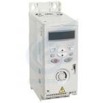
22kW Variable Frequency Drive Inverter ACS355 Three Phase Frequency Converter |
|
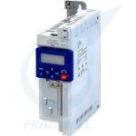
I510 Cabinet Frequency Converter Inverter 0.25kW-15kW Frequency Drive Inverter |
|
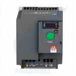
ATV310 Ac Frequency Converter 0.37kW-30kW VFD Inverter 3 Phase |
|
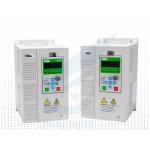
NE200/NE300 AC Frequency Converter VFD Inverter Drive 0.4KW-900KW |

|
FR-E800 Networked Vector Frequency Converter 0.4-22kW VFD Single Phase To Three Phase |
|
M701 High Performance Inverter 200V-690V Rock Solid In Harsh Environments |
Email to this supplier