XHSB505DS
I .Description XHSB505DS live cable identification instrument, also known as cable
identification instrument, multi-function cable identification
instrument, and intelligent cable identification instrument, is
designed for power cable engineers and cable workers to solve the
technical problems of cable identification. The user can accurately
identify one of the target cables from the multiple cables through
the instrument, so as to avoid accidentally sawing the live cables
and causing serious accidents. The cable identification starts from
the operation at both ends of the cable. The double numbering at
both ends of the cable must be ensured to be accurate. This
instrument is designed with PSK technology combined with precise
algorithms. No matter how reliable the memory of on-site staff is,
it cannot replace the recognition of professional instruments. This
product also has the functions of live cable identification, power
failure cable identification, AC current test, and AC voltage test.
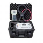
It is composed of a transmitter, a transmitting current clamp, a
receiver, and a receiving flexible current clamp.
Transmitter: It transmits signals to the target cable during the identification
of live cables and power-off cables. Built-in high-performance
rechargeable lithium battery, automatic impedance matching, and
automatic protection. The transmitter adopts an integrated special
toolbox design, uses polypropylene plastic as raw material, and
adds new composite fillers for one-time injection molding. It has
low density, strength, rigidity, hardness, wear resistance, heat
resistance, and insulation performance. The cabinet can withstand a
pressure of about 200kg, the host's large LCD displays the
remaining battery power in real time, white backlight, and dynamic
indication of the emission signal, which is clear at a glance.
Transmitting clamp: When the live cable is identified, the transmitting clamp couples
the signal from the transmitter to the target cable. The jaw size
is Φ120mm. The transmitting clamp has directivity. The transmitting
signal flows in from the direction indicated by the arrow on the
transmitting clamp.
During live identification: use calipers to couple output pulse currents, emit four
frequencies: 625Hz, 1562Hz, 2500Hz, 10kHz, couple to the target
cable (target cable is a three-core armored cable) through the
transmitter, and inject composite pulses into the cable core
Current signal, the pulse current generates an electromagnetic
field around the target cable for the receiver and flexible current
clamp to detect and identify; because the pulse current is
directional, the detection is also directional.
When power failure identification: Directly connected output pulse current is used to inject pulse
encoding current signal into the cable core. This current generates
an electromagnetic field around the target cable for the receiver
and flexible current clamp to detect, decode, and identify; because
the current has directivity, so detection is also directional.
Receiver: It is a handheld device, 3.5-inch color LCD screen, built-in
high-speed microprocessor, combined with precise algorithms, to
identify and decode the pulse code current signal of the
transmitter, and has a signal strength calibration function to
display signal strength and detection results. Exquisite and
intuitive; dynamic display of color scale bars, clear at a glance,
successful cable identification check mark, non-target cable check
mark, can quickly and automatically identify the target cable. At
the same time, the testable voltage range is AC 0.00V~600V
(50Hz/60Hz), the measurable AC current range is AC 0.00A~5000A
(50Hz/60Hz), and the measurable current frequency is 45Hz~70Hz.
Flexible current clamp: It is a Rockwell coil with excellent transient tracking ability,
can quickly identify the pulse code current generated by the
transmitter, and is suitable for thick cables or irregularly shaped
conductors. The inner diameter of the jaw is about 200mm, and it
can clamp cables below Φ200mm, without disconnecting the tested
circuit, non-contact measurement, safe and fast.
Special note: This cable identification instrument has both live cable
identification and power failure cable identification functions.
When power failure cable identification, it is strictly forbidden
to connect to the live cable. Live cable identification is only
applicable to three-core armored cables. When identifying, the
transmitting clamp and receiving clamp cannot be mixed, and the
direction of the input signal must be consistent.
II. Technical specifications - Baseline conditions and working conditions
| Influence | Baseline | working | Remarks | | Ambient temperature | 23℃±1℃ | -10℃~40℃ | / | | Environmental wetness | 40%~60% | <80% | / | | Measured voltage and current frequency | 50Hz±1Hz | 45Hz~70Hz | When testing voltage and current | | Receiver working voltage | 7.4V±0.5V | 7.4V±1V | / | | Transmitter operating voltage | 11.1V±0.5V | 11.1V±1.5V | / | | External electric field, magnetic field | Should be avoided | | Location of the cable under test | The cable under test is at the approximate geometric center of the
flexible current clamp |
- Transmitter specifications
| Function | Transmit a composite pulse frequency current signal, display the
remaining battery voltage, and dynamically indicate the
transmission status | | Power supply | 11.1V large-capacity rechargeable lithium battery, fully charged
and continuously working for about 8 hours | | Output method | Caliper coupling during power-on recognition; direct output during
power-off recognition | | Transmit frequency | 625Hz, 1562Hz, 2500Hz, 10KHz (when electrified identification),
press the up and down arrow keys to adjust the transmission
frequency | | Pulse voltage | 500V (when power failure is recognized) | | Pulse current | Maximum 5A (depending on the size of the loop resistance) | | Pulse frequency | 1 time/sec | | Pulse Width | 2ms | | Launch clamp inner diameter | φ120mm | | Test line length | 3 meters, with alligator clip, 1 red and black each | | Launch clamp size | Length, width and thickness 300mm×175mm×50mm | | Launch clamp inner diameter | φ120mm | | Launching clamp wire length | 2m | | Ground pin size | Length, width and thickness 225mm×100mm×10mm | | Transmitter size | 320mm×275mm×145mm | | Launch clamp size | Length, width and thickness 300mm×175mm×50mm | | Display mode | Large LCD displays the remaining battery voltage in real time, with
backlight | | LCD size | Length and width 128mm×75mm; display area 124mm×67mm | | Package size | Length, width and height 400mm×245mm×335mm | | Operating temperature | -10℃~40℃ | | Storage conditions | -20℃~50℃,≤95%RH, No condensation | | Backlight control | Yes, white backlight | | Operating temperature | -10℃~40℃ | | Storage conditions | -20℃~50℃,≤95%RH, No condensation | | Battery power | When the battery voltage is lower than 9.65V, the battery voltage
low icon is displayed to remind you to charge the battery; when the
battery voltage is lower than 9.5V, the device automatically shuts
down | | Charger | 12.6V DC charger | | Charging port | Round charging port, DC logo | | Compressive | The transmitter adopts an integrated special toolbox design, and
the box can withstand a pressure of about 200kg | | Withstand voltage | AC 3700V/rms (before the top and bottom of the instrument box) | Electromagnetic properties | IEC61326(EMC) | | IEC61010-1(CAT Ⅲ 300V,CAT IV 150V, Pollution level 2) |
| Function | Live cable identification, power failure cable identification; AC
voltage, current, frequency measurement | | power supply | 7.4V large-capacity rechargeable lithium battery, USB charging
interface, fully charged and continuous work for about 6 hours | | Rated current | About 300mA max | | Display mode | 3.5 inch true color LCD screen display, color icon indication | | Signal calibration | Yes, calibrate the transmitted signal. The current percentage
between the received signal and the transmitted signal is between
75% and 135% of the calibration value, which is one of the
conditions for successful identification | | After calibration, the test frequency and magnification cannot be
changed, otherwise it will need to be re-calibrated; different
cables need to be re-calibrated when testing different cables | | Direction recognition | Yes, the transmitting clamp, receiving clamp and loading signal
must be in the same direction, which is one of the conditions for
successful identification | | Cable identification is successful | Green tick icon indicates (√) | | Non-target cable | Red-orange crossed icon indicates (×) | | Receiver size | Length, width and thickness 207mm×101mm×45mm | | Flexible current clamp | The length is about 630mm, the wire diameter is 6 mm or 12.5mm | | Coil inner diameter | φ200mm (larger diameter can be customized according to needs) | | Lead length | Flexible current clamp lead length: 2m | | Voltage test line | 1m long (1 each for red and black) | | scope of test | Power failure recognition: The coil can detect pulse signals with a
loop resistance of 0Ω~10kΩ; when the detection loop resistance is
10kΩ, the transmitter battery must be guaranteed to be above 11V
(generally it can reach a cable length of 0-10 kilometers, mainly
by grounding resistance and wire Cable resistance) | | Live identification: The coil can detect pulse signals with a loop
resistance of 0Ω~200Ω; when the detection loop resistance is 200Ω,
the transmitter battery must be guaranteed to be above 11V
(generally it can reach a cable length of 0-5 kilometers, mainly by
grounding resistance and wire Cable resistance) | | Measuring range | AC voltage : 0.00V~600V(50Hz/60Hz) | | AC current:: 0.00A~5000A(50Hz/60Hz) | | Current frequency : 45Hz~70Hz | | Precision | AC voltage :±2%±3dgt | | AC current :±2%±3dgt | | Current frequency :±2%±3dgt | | Identification signal | Color signal amplitude and digital display | | Detection rate | About 1 time/sec | | Gain adjustment | In the test interface, press the left and right arrow keys to
adjust the signal magnification, the signal amplitude bar is at
10~100, the best | | Backlight control | In the boot function selection interface, press the up and down
arrow keys to adjust the brightness of the LCD backlight | | Automatic shut-down | About 30 minutes after power on, the meter will automatically shut
down to reduce battery consumption | | battery voltage | When the battery voltage is lower than 6.5V, the battery voltage
low icon is displayed, reminding to charge the battery | | charger | 9V DC charger | | Charging port | USB charging port | | Working temperature and humidity | -10℃~40℃; below 80%Rh | | Storage temperature and humidity | -10℃~50℃,≤95%RH, No condensation | | Withstand voltage | AC2000V/rms (before the front and rear ends of the housing) | | Suitable for safety regulations | IEC61010-1 CAT Ⅲ 600V, IEC61010-031, IEC61326, pollution degree 2 |
|