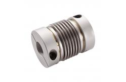
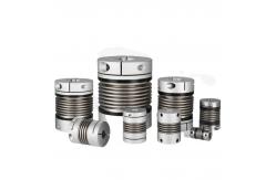
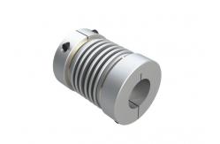
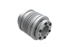
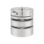
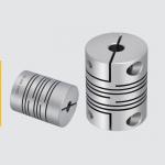
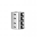
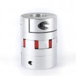
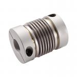
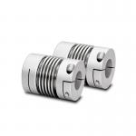
High Precision Shaft Coupler Silver Flex Shaft Coupling Customized
Transmitting the motion and torque of power sources such as motors and engines to
the load end of the equipment is a crucial part of power transmission. Industrial production equipment (such as paper machines,
printing presses, etc.), transportation equipment (such as cars,
ships, etc.), and wind power generation equipment all rely on
couplings to achieve the transfer of power from the power source to
the working components.
Characteristics
High transmission efficiency,It has the function of overload
protection,High transmission efficiency
Parameter Table
| Model | Aperture |
| D | L | L1/L2 | E | F | G | R | Permissible deviation | Allowable(min⁻¹) | Torsional stiffness (N.m/rad) | Net weight (g) | Torque (N.m) |
| d1 | d2 | Axial direction | radial | Angular direction | Min | Max |
| the smallest | the largest | the smallest | the largest |
| BW16 | 4 | 8 | 4 | 8 | 16 | 30 | 9.2 | 9.5 | 3.5 |
| - | ±0.30 | 0.1 | 1.5 | 20000 | 100 | 8 | 0.8 | 1.6 |
| BW16C | 4 | 7 | 4 | 7 | 16 | 30 | 10.5 | 3.8 |
| M3 | ±0.30 | 0.1 | 1.5 | 18000 | 100 | 8 | 0.8 | 1.6 |
| BW20 | 5 | 12 | 5 | 12 | 20 | 29 | 10.5 | 12.5 | 2.7 |
| - | ±0.35 | 0.15 | 2 | 15000 | 160 | 12 | 1.5 | 3 |
| BW20C | 5 | 12 | 5 | 12 | 20 | 33 | 11.7 | 3.5 |
| M3 | ±0.35 | 0.15 | 2 | 13000 | 160 | 18 | 1.5 | 3 |
| BW25 | 5 | 14 | 5 | 14 | 25 | 34 | 11.8 | 16 | 3.8 |
| - | ±0.40 | 0.15 | 2 | 13000 | 220 | 28 | 2 | 4 |
| BW25C | 5 | 12 | 5 | 12 | 25 | 38 | 11.4 | 4.7 |
| M4 | ±0.40 | 0.15 | 2 | 11000 | 220 | 38 | 2 | 4 |
| BW32 | 6 | 16 | 6 | 16 | 32 | 37 | 10.5 | 21 | 3.2 |
| - | ±0.50 | 0.2 | 2 | 10000 | 310 | 46 | 2.5 | 5 |
| BW32C | 6 | 16 | 6 | 16 | 32 | 43 | 13 | 4.5 |
| M4 | ±0.50 | 0.2 | 2 | 10000 | 310 | 56 | 2.5 | 5 |
| BW40 | 8 | 20 | 8 | 20 | 40 | 51 | 15 | 28 | 4.9 |
| - | ±0.60 | 0.2 | 2 | 8000 | 520 | 88 | 10 | 20 |
| BW40C | 8 | 20 | 8 | 20 | 40 | 62 | 20.5 | 6.8 |
| M5 | ±0.60 | 0.2 | 2 | 8000 | 520 | 108 | 10 | 20 |
| BW55 | 10 | 30 | 10 | 30 | 55 | 57 | 14.5 | 38 | 3.3 |
| - | ±0.80 | 0.2 | 2 | 6000 | 850 | 230 | 25 | 50 |
| BW55C | 10 | 30 | 10 | 30 | 55 | 72 | 22.5 | 6.5 |
| M6 | ±0.80 | 0.2 | 2 | 6000 | 850 | 280 | 25 | 50 |
| BW65C | 14 | 38 | 14 | 38 | 65 | 81 | 25.5 | 45 | 7.5 |
| M8 | ±0.80 | 0.2 | 2 | 4500 | 960 | 420 | 60 | 120 |
| BW82C | 14 | 42 | 14 | 42 | 82 | 103 | 34 | 56 | 10 |
| M8 | ±1.0 | 0.2 | 2 | 4000 | 1290 | 850 | 80 | 160 |
matters need attention
Installation Operations
Precise Alignment: Ensure strict alignment of the two shafts during
installation, and control the deviation within the allowable range
(generally, the radial deviation ≤ 0.05mm and the angular deviation
≤ 0.1°). A dial indicator or laser alignment instrument can be used
for calibration to avoid problems such as vibration, bearing wear,
and shaft breakage caused by deviation.