
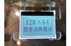
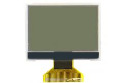
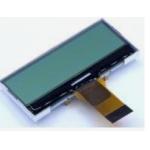
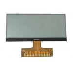
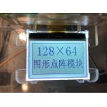
128X64 FSTN LCD Cog Display Lightweight 32PIN Chip On Glass LCD Display
|
|
128X64 FSTN LCD Cog Display Lightweight 32PIN Chip On Glass LCD Display General Specification:
Packaging & Shipping:
Packaging: Carton boxess, Cupboard , EPE, Blister Tray, About the package way, it is up to the size of products, according to customer request and demand. Different countries have not same requirement..
Shipping: Express way as DHL,Fedex,EMS,UPS,air shipping,sea shipping,Any shipping method you prefer. Payment Method:
FAQ: 1. I want the LCD display 8 digits and the outline size is 65x30x2.8mm………? Answer: No problem. Firstly, please kindly send us your specification/ drawing paper If you have not the specification, you can also provide your samples; we will recommend the suitable one if it is standard products. Or we can customize for you based on your own requirement.
a new LCD glass module is need. We have to open new tooling for you.
of the LCD display, display information( Glass thickness, Polarizer, Display Type, Connector mode,
we can report you the exact time when you confirm the drawing paper.
special ones, the leading time is about 15-30 days. suppose we can finish earlier, we will report the information in advanced.
Our Services: 1. Free repair within one year after the shipment of products from us. 2. Replacement within 30 days after the shipment of products from us due to products' problems. can offer us good discounts. 8.Products pictures only for your reference. please kindly refer to the specification. we can provide the products basic on the specification. or you can offer your own specification or drawing , we can customize all kinds of LCD displays for you. thanks for your kind support always.
Product application
Household appliances-refrigerators: air conditioners, fans, hot and cold air heaters, water heaters, electric blankets, heaters, air purifiers, washing machines, clothes dryers, vacuum cleaners, lampblack cleaners, microwave ovens, cookers, electric ovens, rice cookers, water drinkers, tea sets, etc.;
Communication :equipment-telephone, interphone, fax machine, wireless wifi, etc.
Automotive: electronics-on-board entertainment system, automobile fault detector, CarLog, vehicle navigator, car audio, reverse radar, reverse mirror, camera, anti-theft device, etc.
Instruments :water meters, electric meters, multimeter, electronic scales, pressure meters, temperature meters, flow meters, display instruments, electrical instruments, space instruments, measuring instruments, analytical instruments, electrochemical instruments, optical instruments, etc.;
Fitness: equipment-treadmill, waist machine, fitness bike, training device, pedometer, code table, beauty instrument, fat square measuring instrument, fitness instrument, electronic sphygmomanometer, weighing scale, etc.
Financial :tax control-tax control cash machine, poss machine, usb-key cheque printer, banknote counting machine, tax control invoice machine, etc.
Consumer electronics:mp3,mp4,dvd, electronic dictionary, click reader, early teaching machine, learning machine, electronic organ, electronic clock, chronograph, calculator, etc.
high resolution, high definition, high brightness, cost-effective, energy conservation, high temperature, low temperature, Wide Temperature Range, Positive, Negative
List of Exiting COB LCD Modules:
|
||||||||||||||||||||||||||||||||||||||||||||||||||||||||||||||||||||||||||||||||||||||||||||||||||||||||||||||||||||||||||||||||||||||||||||||||||||||||||||||||||||||||||||||||||||||||||||||||||||||||||||||||||||||||||||||||||||||||||||||||||||||||||||||||||||||||||||||||||||||||||||||||||||||||||||||||||||||||||||||||||||||||||||||||||||||||||||||||||||||||||||||||||||||||||||||||||||||||||||||||||||||||||||||||||||||||||||||||||||||||||||||||||||||||||||||||||||||||||||||||||||||||||||||||||||||||||||||||||||||||||||||||||||||||||||||||||||||
| Product Tags: FSTN LCD Cog Display LCD Cog Display Lightweight 32PIN Chip On Glass LCD Display |


|
28 Pins COG LCD Module White LED Backlight Transflective Mono LCD Display |
|
28 Pins COG LCD Module White LED Backlight Transflective Mono COG LCD Display Screen |
|
128X64 FSTN LCD Cog Display Lightweight 32PIN Chip On Glass LCD Display |
|
COG+PIN Black Segmented LCD Display ST7035 I2C LCD Transmissive Screen |
|
COG FPC VA LCD Segment Display White On Black SPI Interface For Rangefinder |
|
32PIN COG LCD Display 3.3V VTN NEGATIVE 1/32DUTY 1/6BIAS 9.5V ST7567 |