
LKAV1615 1.5km EOG UGV FHD Video & Data COFDM Video Transmitter
|


|
1.5km UGV Video Transmitter FHD Video & Data COFDM H.264 AES256 Encryption
Introduction The LKAV-1615 is a powerful COFDM wireless transmitter specially designed for UGV/Robots applications. It integrates video multiplexing, video sending and data stream sending/receiving. It supports variety video modes, H.264 encoding, various modes adaptive, resolution up to 1080P, bright colors, low latency, and smooth video. The built-in data module can receive data sent by the control station, process and execute it. It also supports some peripheral sensing devices such as gas sensors, detectors, etc. The detected data is transmitted back to the control station and displayed in real time, which is convenient for commanders to make timely judgments.
Features ■ Video stream frequency 200-800MHz ■ Data stream frequency 410-500MHz ■ Output power 2W (Video) ■ Range covers 1-3km LOS ■ 2-8MHz bandwidth adjustable ■ Advance COFDM and H.264 video compression technologies ■ RS232/485/TTL for selection ■ High video quality and supports multiple video formats ■ Rugged aluminum alloy enclosure
Specification
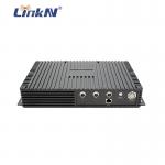
Panel Description 1. Power Input & Data Port - DC 12V/5A, RS232 2. Sensor Port - Gas sensor data interface (RS232) 3. MIC Port – Audio input 4. VIDEO1 Port – BNC interface, Video input 1 (Visible Light) 5. VIDEO2 Port – BNC interface, Video input 2 (Infrared) 6. VIDEO3 Port – BNC interface, Video input 3 (Fisheye) 7. RF-D Antenna Interface – N female, data sending/receiving 8. USB Interface – Connect with the control box to adjust parameters 9. Video Stream Indicator – lights red when power on, and flashes green light during normal work, the stronger the signal, the faster the flash. 10. RF-V Antenna Interface – N female, video sending
Communication Protocol UGV Driver Board Communication Protocol When using RS232 bus to connect to the device, the following protocol format is followed: Baud rate: 19200; Configuration: 1 stop bit, 8 data bits, no parity check; Sending cycle: 100ms, sending data regularly; Note: The data is sent from the control board of the UGV;
The format is as follows:
The detailed definition is as follows: ■ Frame header: 1 byte, fixed to 0x7e. ■ Source: 1 byte, fixed to 0x02. ■ Destination: 1 byte, fixed to 0x03. ■ Heartbeat: 1 byte. The heartbeat value is increased by 1 before data is sent, which is used as the judgment of new data. If the heartbeat of the receiving end does not change, the data is not updated. The maximum value is 249, and it is reset to zero after reaching the maximum value. ■ CMD1 data: 1 byte.
Bit0: Vehicle travel control switch bit. When the value is 1, the vehicle travel control is on; when it is 0, the vehicle travel control is off. Bit1: Headlight switch bit. When it is 1, the headlight is on; when it is 0, the headlight is off. Bit2: Emergency stop switch bit. Emergency stop is on when it is 1, and it works normally when it is 0. Bit3: Water inlet valve switch bit, when it is 1, the valve is open, when it is 0, the valve is closed. Bit4: high and low speed bits, high speed when 1 and low speed when 0 Bit5: Alarm bit. When this bit is 1, the alarm is issued. When it is 0, the alarm is canceled. Bit6: This bit is 0. Bit7: This bit is 0.
■ CMD2 data: 1 byte.
Bit0: picture mode, four-in-one picture and single picture are switched each other. When this bit is 1, it means the video mode needs to be switched, and when it is 0, it means it is invalid. Bit1: It means to switch the screen. When this bit is 1, it means to switch the next video screen. When it is 0, it means it is invalid. Bit2: OSD control bit. When this bit is 1, the OSD is on, and when it is 0, the OSD is off. Bit3: Start recording video. When this bit is 1, it means to start recording video, when it is 0, it means to stop recording. Bit4: Spray mode. When this bit is 1, the spray mode is turned on, and when it is 0, the spray mode is turned off. Bit5: Automatic fire finding mode. When this bit is 1, it means that the automatic fire finding mode is on, and when it is 0, it means it is off. Bit6: This bit is 0. Bit7: This bit is 0.
■ CMD3 data: 1 byte.
Bit0-Bit7: 0.
■ Drive 1 data: 1 byte, data 0 ~ 127 means walking backward, 128 ~ 255 means walk forward. In fact, in order to prevent misoperation, the data value of walking backward is 0 ~ 100 and the data value of walking forward is 150 ~ 250. The parsing end can judge the data forward or backward. The value can be adjusted as a speed value (100 levels). If it is designed to walk at a uniform speed, only the direction can be determined.
■ Drive 2 data: 1 byte. The data from 0 to 127 indicates walking to the left, and 128 to 250 indicates walking to the right. Actually, in order to prevent misoperation, the data value of walking left is 0 ~ 100 and the data value of walking right is 150 ~ 250. The parsing end can judge the data to the left or right. The size of the value can be adjusted as a speed value (100 levels). If it is designed to walk at a uniform speed, only the direction can be determined.
■ PTZ control data: 1 byte.
Bit0: PTZ control switch bit. When it is 1, the PTZ is controlled. When it is 0, it is invalid and stops. Bit1: When it is 1, the gimbal rotates to the left; when it is 0, it is invalid and stops. Bit2: When it is 1, the gimbal rotates to the right; when it is 0, it is invalid and stops. Bit3: When it is 1, the gimbal rotates upward; when it is 0, it is invalid and stops. Bit4: When it is 1, the gimbal rotates downward; when it is 0, it is invalid and stops. Bit5: PTZ rises when it is 1; it is invalid when it is 0, it stops. Bit6: The gimbal descends when it is 1; it is invalid when it is 0 and stops. Bit7: PTZ reset bit. When it is 1, the PTZ is restored to initialization.
■ Water cannon control data: 1 byte.
Bit0: Water cannon start bit. Water cannon starts when it is 1; it is invalid when it is 0. Bit1: When it is 1, the water cannon is turned to the left; when it is 0, it is invalid and stops. Bit2: When it is 1, the water cannon rotates to the right; when it is 0, it is invalid and stops. Bit3: The water cannon rotates upward when it is 1; it is invalid when it is 0, and it stops. Bit4: The water cannon rotates downward when it is 1; it is invalid when it is 0, it stops. Bit5: The water cannon is turned on when it is 1, and it is turned off when it is 0. Bit6: The water cannon rises when it is 1; it is invalid when it is 0, it stops Bit7: The water cannon descends when it is 1; it is invalid when it is 0 and stops
■ Reserve 1 and Reserve 2: These are reserved values and can be set to 0. ■ Check: The result of exclusive OR of all the bytes of data before the check byte. ■ End of frame: 2 bytes, 0x0d and 0x0a respectively.
Note: Among the data sent by the car-side control board to the car-side drive board, the data not needed by the drive board is returned to the car-side control board as it is.
UGV Control Board Communication Protocol
■ Baud rate: 19200 ■ Configuration: 1 stop bit, 8 data bits, no parity ■ Sending cycle: 100ms, sending data regularly
Note: The data is sent by UGV driver board.
The format is as follows:
Detailed description:
■ Frame header: 1 byte, fixed to 0x7e. ■ Source address: 1 byte, fixed to 0x03. ■ Destination address: 1 byte, fixed to 0x02. ■ Heartbeat: 1 byte. The heartbeat value is increased by 1 before data is sent, which is used as the judgment of new data. If the heartbeat of the receiving end does not change, the data is not updated. The maximum value is 249, and it is reset to zero after reaching the maximum value. ■ CMD1:
Bit0: Vehicle travel control switch bit. When the value is 1, the vehicle travel control is on; when it is 0, the vehicle travel control is off. Bit1: PTZ start bit. When the value is 1, it means the PTZ starts, when it is 0, it means it stops. Bit2: Water cannon start bit. When the value is 1, the water cannon is started, and when it is 0, the water cannon is stopped. Bit3: High and low speed bits, high speed when 1 and low speed when 0. Bit4: Auto-pendulum mode bit. When it is 1, it means that the auto-pendulum mode is on, and when it is 0, it means it is off. Bit5: Spray mode bit. When it is 1, it indicates that the spray mode is on, and when it is 0, it indicates that it is off. Bit6: Automatic fire detection position. When it is 1, it means that the automatic fire detection mode is on, and when it is 0, it means that the automatic fire detection mode is off. Bit7: This bit is 0.
■ CMD2:
Bit0: Headlight switch signal. When the value is 1, the headlights are turned on. When the value is 0, the headlights are off. Bit1: Alarm signal switch bit. When the value is 1, it indicates that the alarm has been turned on. When it is 0, it indicates that the alarm is turned off. Bit2 ~ Bit7: Reserved, it is 0.
■ Battery percentage: 2 bytes, an unsigned integer value, ranging from 0 to 100. Unit:%, which indicates the battery percentage. ■ Battery temperature: 2 bytes, an unsigned integer value, ranging from 0 to 100, unit: ° C, which represents the battery temperature value. ■ Ambient temperature: 2 bytes, unsigned integer value, ranging from 0 to 100, unit: ° C, which represents the ambient temperature value. ■ Battery current: 2 bytes, an unsigned integer value, ranging from 0 to 100, unit: A, which represents the battery current value. ■ Vehicle speed: 2 bytes, an unsigned integer value, ranging from 0 to 50, unit: m / s, which represents the vehicle speed value. Note that in order to represent a decimal value, this value is the real speed value multiplied by 10. After the value. ■ Radar ranging: 2 bytes, an unsigned integer value, ranging from 0 to 500, unit: m, which represents the distance value. Note that in order to represent two decimal places, this value is the real speed value multiplied by 100. After the value. ■ Left and right tilt angle: 2 bytes, signed integer value, value range: -1000 ~ + 1000, unit °, which means the left and right tilt angle value. Note: In order to represent a decimal value, this value is the true angle value. Multiplied by 10. ■ Fore and aft pitch angle: 2 bytes, signed integer value, value range: -1000 ~ + 1000, unit °, which means the inclination angle value. Note: In order to represent a decimal value, this value is the true angle value. Multiplied by 10. ■ Check: The result of exclusive OR of all the bytes of data before the check byte. ■ End of frame: 2 bytes, 0x0d and 0x0a respectively.
UGV Gas Sensor Communication Protocol ■ Data: data of 6 gas sensors can be connected (gas types can be increased) ■ Format: Baud rate: 9600. Configuration: 1 stop bit, 8 data bits, no parity. ■ Sending cycle: 100ms, sending data on a regular basis. Note: The gas sensor data is issued by the customer.
The format is as follows:
The detailed definition is as follows: ■ Frame header: 1 byte, fixed to 0x7e. ■ Source: 1 byte, fixed at 0x05. ■ Destination: 1 byte, fixed to 0x04. ■ Heartbeat: 1 byte. The heartbeat value is increased by 1 before data is sent, which is used as the judgment of new data. If the heartbeat of the receiving end does not change, the data is not updated. The maximum value is 249, and it is reset to zero after reaching the maximum value. ■ Oxygen: 2 bytes, an unsigned integer value, ranging from 0 to 1000. The default value is 0, which means the percentage value of oxygen concentration, the unit is%. Note: In order to express the accuracy of one decimal place, this value is multiplied by 10 and then transmitted. Carbon monoxide: 2 bytes, an unsigned integer value, ranging from 0 to 1000. The default value is 0, which means the concentration of carbon monoxide. The unit is ppm. ■ Ammonia gas: 2 bytes, an unsigned integer value, ranging from 0 to 100. The default value is 0, which indicates the concentration of ammonia gas. The unit is ppm. ■ Hydrogen sulfide: 2 bytes, an unsigned integer value, ranging from 0 to 100. The default value is 0, which indicates the concentration of hydrogen sulfide. The unit is ppm. ■ Sulfur dioxide: 2 bytes, an unsigned integer value, ranging from 0 to 200. The default value is 0, which indicates the concentration of sulfur dioxide, the unit is ppm. Note: In order to express the accuracy of one decimal place, this value is multiplied by 10 and then transmitted. ■ Chlorine: 2 bytes, an unsigned integer value, ranging from 0 to 100. The default value is 0, which indicates the concentration of chlorine gas in ppm. Note: In order to express the accuracy of one decimal place, this value is multiplied by 10 and then transmitted. ■ Check: 1 byte, which is the result of exclusive OR of all the data in front of the check byte. End of frame: 2 bytes, 0x0d and 0x0a respectively.
Package Content
Advantages of COFDM
As for high-speed data transmission, COFDM has its self-adaptive modulation mechanism which enables subcarriers to choose different modulation methods like QPSK, QAM, 16QAM or 64QAM according to different channel conditions and background noises. If the conditions are good, then adapt itself to the high-efficiency modulation, if the conditions are bad, then adapt to the anti-interference modulation. So it can reliably adapt to a high-speed data transmission.
It has strong Inter-Symbol Interference (ISI) ability, ISI is the major interference besides noise in digital communications. COFDM by using the cyclic prefix has the strong ability of ISI.
Ease of use in combination with a variety of other methods, COFDM can be used as a modulation method, besides, it can be easily combined with many kinds of multiple access technology, providing access for multiple users at the same time. You can allow multiple users to simultaneously use the COFDM information technology for transmission.
Applications of COFDM Device
High-speed Real-time Mobile Wireless Transmission
Real-time Maritime Wireless Transmission
Live Broadcasting Video Transmission
Public Mobile Communication System
As a conclusion, COFDM modulation solved the difficult problems of "Non-line of Sight" and "Mobile" wireless broadband transmission when speed is over 2Mbps, COFDM can capture videos at high speed and transmit high quality real time videos, make users gain exceptional freedom in news collecting, live broadcasting, real-time monitoring applications.
FAQ Q1: Are you a manufacturer or a trading company? We're professional manufacturer specializing in wireless transmission systems. Q2: Why should I choose you? You'll get competitive price, prime quality, satisfied service and long warranty. Q3: What kind of product service can I have? OEM & ODM service. Q4: What kind of warranty do you offer? We offer one-year-warranty and lifelong maintenance. Q5: What're the payment terms? We accept bank transfer, PayPal, or cash payment. Q6: Packaging & Shipping? Q7: How long for delivery? Q8: Can I order 1 sample for test? Yes, we welcome sample order, mixed samples are acceptable. Q9: Do you have any MOQ limit? No limit, 1pc is acceptable. Q10: Is it OK to print my logo on the product? Yes, please inform us formally before production and confirm the design firstly
About LinkAV
Our Advantages ■ Over 15 years experiences in wireless communication solutions. ■ High product quality, competitive price and low MOQ ■ Excellent pre-sale and after-sale technical team. ■ Quick response and fast delivery. ■ OEM supported.
Youtube: https://www.youtube.com/channel/UCn0iKGgxQtkpi2qG4U0HsZg Official Website: http://www.LinkAVtech.com LinkedIn: https://www.linkedin.com/company/linkav-technology/ Facebook: https://www.facebook.com/LinkAVtech/
|
||||||||||||||||||||||||||||||||||||||||||||||||||||||||||||||||||||||||||||||||||||||||||||||||||||||||||||||||||||||||||||||||||||||||||||||||||||||||||||||||||||||||||||||||||||||||||||||||||||||||||||||||||||||||||||||||||||||||||||||||||||||||||||||||||||||||||||||||||||||||||||||||||||||||||||||||||||||||||||||||||||||||||||||||||||||||||||||||||||||||||||||||||||||||||||||||||||||||
| Product Tags: wireless audio video sender cofdm video transmitter | ||||||||||||||||||||||||||||||||||||||||||||||||||||||||||||||||||||||||||||||||||||||||||||||||||||||||||||||||||||||||||||||||||||||||||||||||||||||||||||||||||||||||||||||||||||||||||||||||||||||||||||||||||||||||||||||||||||||||||||||||||||||||||||||||||||||||||||||||||||||||||||||||||||||||||||||||||||||||||||||||||||||||||||||||||||||||||||||||||||||||||||||||||||||||||||||||||||||||

|
LKAV3109 5km Industrial UGV Controller Handheld Smart MIMO RF Remote Controller |

|
LKAV3624&3203 Long Range UGV Video Data Link AES Encrytion Wireless Video Transmission System |
|
LKAV3624 1.5km UGV Video Data Link AHD IP Video Input Built in DVR Rugged housing |

|
LKAV3624 8 Channel Video Transmission System Audio Embedding 2km NLOS CAN Control |

|
LKAV3624 2km Video Data Link CAN Control Video Transmission System For Excavator Loader UGV |

|
LKAV3109 Waterproof Industrial 10.1 Inch Display UGV EOD Robots Remote Controller |