Products Description In automatic mode, when any detector senses a fire, it
immediately transmits a signal to the control panel. The control
panel then activates the audible and visual alarm devices, starts
the exhaust fans, disconnects non‑essential power supplies, and
sends a command to recall all elevators. If a person discovers the
fire, they can press a manual call point to trigger the same
sequence. For areas protected by a gas‑based fire suppression system,
the release sequence begins only after two independent detectors have been activated. Once this condition is met, a
pre‑determined delay timer starts. After the delay elapses, the
extinguishing gas is released, and the release indicator lights
illuminate to clearly warn people not to enter the protected area.
All these functions work together to ensure fast fire detection and safe occupant evacuation.
|
1. Detection Layer (Sensors)The detection layer acts as the sensory system of the fire alarm
installation. It includes smoke detectors, heat detectors, and
combined smoke‑and‑heat detectors. Smoke detectors sense changes in air caused by combustion and are ideal for
offices, hotels, and corridors. Heat detectors monitor temperature increases and are well suited for
kitchens, car parks, and plant rooms. Combined detectors use both smoke and heat sensing to reduce false alarms,
making them a preferred choice for hospitals and premium commercial
buildings. Beam smoke detectors are recommended for large‑volume spaces such as warehouses,
atriums, and sports stadiums. Flame detectors should be used in high‑risk areas, including oil depots, fuel
storage zones, and chemical plants.
| | 2. Input Layer (Manual and Monitoring Equipment)This layer enables manual initiation and external equipment
monitoring. It consists of manual call points, input modules,
short‑circuit isolators, and fire telephone sockets. Manual call points are installed near exits, staircases, and common areas,
allowing anyone to manually trigger an alarm. Input modules receive status signals from external devices, such as water
flow switches, pressure switches, and control valves. Short‑circuit isolators automatically disconnect faulty sections of the loop,
ensuring the rest of the system remains operational. Fire telephone sockets enable direct communication between firefighters and the
central control panel during an emergency.
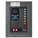
| | 3. Control Layer (The “Brain” of the System)The control layer is the central intelligence of the entire fire
alarm system. Its main components are the Fire Alarm Control Panel (FACP) and the Gas Suppression Control Panel. The FACP receives signals from all detectors and modules, decides when
to generate alarms, and activates all connected field devices. The Gas Suppression Control Panel is specially designed for FM200, IG541, CO₂, and other clean
agent systems. It supports functions such as delay before release, manual/automatic mode selection, and pressure switch monitoring. Additional control devices include repeater panels for displaying alarms on different floors and fire broadcast control panels for playing pre‑recorded or live evacuation messages.
| | . Execution Layer (Alarm and Action Equipment)The execution layer carries out the commands issued by the control
panel. It includes alarm sounder‑strobes, output modules, fire
alarm bells, and gas release indicators. Alarm sounder‑strobes produce high‑audibility sounds and flashing lights to clearly
alert occupants to evacuate. Output modules control external equipment such as exhaust fans, fire
dampers, power cut‑off relays, and elevator recall units. Fire alarm bells offer a cost‑effective solution for conventional or smaller
systems. Gas release indicators are mounted at the entrance of each protected area. They
illuminate when gas is about to be released or has already been
discharged, providing a clear visual warning not to enter.
|
Product Advantages
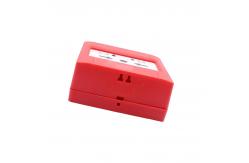
| J-SAP-JBF4121A-Ex Manual Fire Alarm Button
1.Built-in microprocessor, stable performance.
2.Adopts SMT surface mount technology, with high reliability and
good consistency.3.Uses a dual-bus system, without polarity
requirements, ensuring low power consumption while enabling the
transmission distance to reach up to 1000m4.Explosion-proof type is
intrinsically safe, requiring a safety barrier to be connected for
use.5.Electronic coding method, can be addressed through a
dedicated electronic encoder6.Operation is simple. Pressing the
operation panel on the panel can realize reporting fire alarm
to the controller.7.The operation panel of the manual alarm button
needs to be reset after being pressed. This must be done using
adedicated key that matches the button.
8.The manual alarm button adopts a plug-in structure, which is easy
for customers to install, construct and maintain |
Products Parameters
| | Operating environmental conditions |
|---|
| Operating temperature | -10 to +55°C | | Storage temperature | -30 to +75°C | | Relative humidity | ≤ 95% RH (40 ± 2°C) |
| Parameter | Technical Specification |
|---|
| Operating Voltage | DC 18-28V, modulated type provided by controller (must use safety
barrier) | | Standby Current | ≤0.3mA (24V) | | Alarm Current | ≤1mA (24V) | | Explosion-proof Mark | Ex ib IIC T6 Gb | | Addressing Method | Electronic encoder addressing | | Addressing Range | 1-200 | | Indicator Light | Fire indicator flashes momentarily in standby mode; stays steady
red when pressed and in alarm | | Dimensions | 90mm (L) × 90mm (W) × 52mm (H) | | Wiring System | Two-wire bus, non-polarity |
|