|
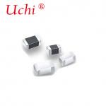
Inrush Current Limiting Power NTC Thermistors For Switch Mode Power Supply Quick Detail: ·Low cost solid state device for inrush current supression.
·Minimise line current distortion and radio noise.
·Protect switches, rectifier diodes and smoothing capacitors against premature failures.
·Prevent fuse from blowing in error. Description: Power NTC thermistor can be a cost effective device to limit the amount of inrush current in a switching power supply or other devices when the power is first turned on. Power NTC thermistor limits surge current by functioning as a power resistor which drops from a high cold resistance to a low hot resistance when heated by the current flowing through it.
Inrush-current limiters power NTC thermistor protect circuits from undesirably high currents, suppressing high inrush current surges, while its resistance remains negligible low during continuous operation. Thanks to their low resistance in the operating state, Power thermistor have a considerably lower power dissipation than the fixed resistors frequently used for this application. Applications: Limiting surge current, suitable for the protection of switch mode power supply, UPS power, transformers, motors, various electric heating utensil, energy saving lights, ballast, various power circuit, amplifiers, colored displayer, monitors, color TV, filament protection, etc.
Power thermistor components can also be used for the soft starting of motors, for example in vacuum cleaners with continuous currents of up to 20 A. Specifications: Inrush Current Limiting Power NTC Thermistor Features: ·Resin coated disk thermistor with uninsulated lead-wires.
·Suitable for both AC and DC circuits up to a voltage of 265 V(rms).
·Wide range of resistance, current and dimension.
·Excellent mechanical strength.
·Suitable for PCB mounting. |  Comparison curve with and without Inrush Current Limiting power NTC thermistor |  Inrush Current Limiting Power NTC thermistor
Load-temperature characteristics | Typical Application of Inrush Current Limiting Power NTC thermistors for Circuit Protection  Basic circuit diagram NTC thermistor for diode protection  Possible locations of NTC Thermistors inrush current limiters  Typical power supply circuit  Power NTC thermistors application circuits  Another example NTC Thermistor for inrush current protection circuit  Inrush Current Limiting Power NTC Thermistors Dimensions (mm)  Inrush Current Limiting Power NTC Thermistors Data Sheet | Part No. | R25
(ohm) | Max
Stable
Current
(A) | Approx.
Resistance
value at
max current
(Ω) | Dissipation
Factor
(mW/oC) | Thermal
Time
Constant
(sec) | Dimensions (mm) | | Dmax | Tmax | H | H 0 | d±1 | | MF72-3D9 | 3 ohm | 4A | 0.120 | 11 | 34 | 11 | 5.5 | 13.5 | 20.5 | 7.5 /5 | | MF72-5D9 | 5 ohm | 3A | 0.210 | 11 | 34 | 11 | 5.5 | 13.5 | 20.5 | 7.5 /5 | | MF72-8D9 | 8 ohm | 2A | 0.400 | 11 | 32 | 11 | 5.5 | 13.5 | 20.5 | 7.5 /5 | | MF72-10D9 | 10 ohm | 2A | 0.458 | 11 | 32 | 11 | 5.5 | 13.5 | 20.5 | 7.5 /5 | | MF72-16D9 | 16 ohm | 1A | 0.802 | 11 | 31 | 11 | 5.5 | 13.5 | 20.5 | 7.5 /5 | | MF72-22D9 | 22 ohm | 1A | 0.950 | 11 | 30 | 11 | 5.5 | 13.5 | 20.5 | 7.5 /5 | | MF72-33D9 | 33 ohm | 1A | 1.124 | 11 | 30 | 11 | 5.5 | 13.5 | 20.5 | 7.5 /5 | | MF72-50D9 | 50 ohm | 1A | 1.252 | 11 | 30 | 11 | 5.5 | 13.5 | 20.5 | 7.5 /5 | | MF72-80D9 | 80 ohm | 0.8A | 2.010 | 11 | 30 | 11 | 5.5 | 13.5 | 20.5 | 7.5 /5 | | MF72-3D11 | 3 ohm | 5A | 0.100 | 13 | 43 | 13 | 5.5 | 15.5 | 22.5 | 7.5 /5 | | MF72-5D11 | 5 ohm | 4A | 0.156 | 13 | 45 | 13 | 5.5 | 15.5 | 22.5 | 7.5 /5 | | MF72-8D11 | 8 ohm | 3A | 0.255 | 14 | 47 | 13 | 5.5 | 15.5 | 22.5 | 7.5 /5 | | MF72-10D11 | 10 ohm | 3A | 0.275 | 14 | 47 | 13 | 5.5 | 15.5 | 22.5 | 7.5 /5 | | MF72-12D11 | 12 ohm | 2A | 0.462 | 14 | 48 | 13 | 5.5 | 15.5 | 22.5 | 7.5 /5 | | MF72-16D11 | 16 ohm | 2A | 0.470 | 14 | 50 | 13 | 5.5 | 15.5 | 22.5 | 7.5 /5 | | MF72-20D11 | 20 ohm | 2A | 0.512 | 15 | 52 | 13 | 5.5 | 15.5 | 22.5 | 7.5 /5 | | MF72-22D11 | 22 ohm | 2A | 0.563 | 15 | 52 | 13 | 5.5 | 15.5 | 22.5 | 7.5 /5 | | MF72-33D11 | 33 ohm | 1.5A | 0.734 | 15 | 52 | 13 | 5.5 | 15.5 | 22.5 | 7.5 /5 | | MF72-50D11 | 50 ohm | 1.5A | 1.021 | 15 | 52 | 13 | 5.5 | 15.5 | 22.5 | 7.5 /5 | | MF72-60D11 | 60 ohm | 1.5A | 1.215 | 15 | 52 | 13 | 5.5 | 15.5 | 22.5 | 7.5 /5 | | MF72-1.3D13 | 1.3 ohm | 7A | 0.062 | 13 | 60 | 15.5 | 6 | 17.5 | 24.5 | 7.5 | | MF72-3D13 | 3 ohm | 6A | 0.092 | 14 | 60 | 15.5 | 6 | 17.5 | 24.5 | 7.5 | | MF72-5D13 | 5 ohm | 5A | 0.125 | 15 | 68 | 15.5 | 6 | 17.5 | 24.5 | 7.5 | | MF72-10D13 | 10 ohm | 4A | 0.206 | 15 | 65 | 15.5 | 6 | 17.5 | 24.5 | 7.5 | | MF72-15D13 | 15 ohm | 3A | 0.335 | 16 | 60 | 15.5 | 6 | 17.5 | 24.5 | 7.5 | | MF72-30D13 | 30 ohm | 2.5A | 0.517 | 16 | 65 | 15.5 | 6 | 17.5 | 24.5 | 7.5 | | MF72-47D13 | 47 ohm | 2A | 0.810 | 17 | 65 | 15.5 | 6 | 17.5 | 24.5 | 7.5 | | MF72-1.3D15 | 1.3 ohm | 8A | 0.048 | 18 | 68 | 17.5 | 6 | 19.5 | 26.5 | 10/7.5 | | MF72-1.5D15 | 1.5 ohm | 8A | 0.052 | 18 | 69 | 17.5 | 6 | 19.5 | 26.5 | 10/7.5 | | MF72-3D15 | 3 ohm | 7A | 0.075 | 18 | 76 | 17.5 | 6 | 19.5 | 26.5 | 10/7.5 | | MF72-5D15 | 5 ohm | 6A | 0.112 | 20 | 76 | 17.5 | 6 | 19.5 | 26.5 | 10/7.5 | | MF72-8D15 | 8 ohm | 5A | 0.178 | 20 | 80 | 17.5 | 6 | 19.5 | 26.5 | 10/7.5 | | MF72-10D15 | 10 ohm | 5A | 0.180 | 21 | 85 | 17.5 | 6 | 19.5 | 26.5 | 10/7.5 | | MF72-15D15 | 15 ohm | 4A | 0.268 | 20 | 75 | 17.5 | 6 | 19.5 | 26.5 | 10/7.5 | | MF72-30D15 | 30 ohm | 3.5A | 0.438 | 18 | 75 | 17.5 | 6 | 19.5 | 26.5 | 10/7.5 | | MF72-47D15 | 47 ohm | 3A | 0.680 | 21 | 86 | 17.5 | 6 | 19.5 | 26.5 | 10/7.5 | | MF72-0.7D20 | 0.7 ohm | 12A | 0.018 | 25 | 89 | 22.5 | 7 | 24.5 | 31.5 | 10/7.5 | | MF72-1.3D20 | 1.3 ohm | 9A | 0.037 | 24 | 88 | 22.5 | 7 | 24.5 | 31.5 | 10/7.5 | | MF72-3D20 | 3 ohm | 8A | 0.055 | 24 | 88 | 22.5 | 7 | 24.5 | 31.5 | 10/7.5 | | MF72-5D20 | 5 ohm | 7A | 0.087 | 23 | 87 | 22.5 | 7 | 24.5 | 31.5 | 10/7.5 | | MF72-8D20 | 8 ohm | 6A | 0.142 | 25 | 105 | 22.5 | 7 | 24.5 | 31.5 | 10/7.5 | | MF72-10D20 | 10 ohm | 6A | 0.162 | 24 | 102 | 22.5 | 7 | 24.5 | 31.5 | 10/7.5 | newly developed inrush current limiting power NTC thermistor increased max. operating current. | Part No. | R25 (ohm) | Max Stable Current (A) | Approx. Resistance Value at Maximum Current (Ω) | Max Rated Power Pmax. (W) | Dissipation Factor (mW/oC) | Thermal Time Constant (s) | Dimensions (mm) | | Dmax | Tmax | H | H 0 | d | Pin form | | D15mm 2.5ohm/9.5A | 2.5 ohm | 9.5A | 0.044 | 3.5W | 22 min | 75 max | 17.5 | 6 | 19.5 | 26.5 | 7.5 | inner kinked | | D15mm 5 ohm/8A | 5 ohm | 8A | 0.058 | 3.5W | 22 min | 75 max | 17.5 | 6 | 19.5 | 26.5 | 7.5 | inner kinked | | D15mm, 10 ohm/7A | 10 ohm | 7A | 0.098 | 3.5W | 22 min | 75 max | 17.5 | 6 | 19.5 | 26.5 | 7.5 | inner kinked | | D20mm 1 ohm/16A | 1 ohm | 16A | 0.027 | 5W | 28 min | 110 max | 22.5 | 7 | 24.7 | / | 10 | straight | | D20mm 5 ohm/12A | 5 ohm | 12A | 0.047 | 5W | 28 min | 110 max | 22.5 | 7 | 24.7 | / | 10 | straight | | D20mm, 10 ohm/8A | 10 ohm | 8A | 0.085 | 5W | 28 min | 110 max | 22.5 | 7 | 24.7 | / | 10 | straight | | D25mm, 1 ohm/20A | 1 ohm | 20A | 0.021 | 7W | 30 min | 130 max | 29 | 8 | 33 | / | 10 | straight | | D25mm , 5 ohm/14A | 5 ohm | 14A | 0.047 | 7W | 30 min | 130 max | 29 | 8 | 33 | / | 10 | straight | | D25mm, 10 ohm/10A | 10 ohm | 10A | 0.084 | 7W | 30 min | 130 max | 29 | 8 | 33 | / | 10 | straight | | D30mm, 1 ohm/30A | 1ohm | 30A | 0.014 | 8W | 40 min | 190 max | 36 | 8.5 | 40 | / | 18 | straight | | D30mm, 10 ohm/13A | 10 ohm | 13A | 0.056 | 8W | 40 min | 190 max | 36 | 8.5 | 40 | / | 18 | straight | Inrush Current Limiting Power NTC thermistor Reliability Data | Test | Standard | Test Conditions | ΔR25/R25 (typical) | Remarks | | Storage in dry heat | IEC 60068-2-2 | Storage at upper category temperature Temperature: 125oC Time: 1000h | <10% | No visible damage | | Storage in damp heat, steady state | IEC 60068-2-3 | Temperature of air: 40oC Relative humidity of air: 93% Duration: 21 days | <5% | No visible damage | | Rapid temperature cycling | IEC 60068-2-14 | Lower test temperature: -55oC Upper test temperature: 125oC Number of cycles: 10 | <10% | No visible damage | | Endurance | | I=Imax t: 1000h | <10% | No visible damage | | Cyclic endurance | | I=Imax, 1000 cycles On-time=1 min Cooling time=6 min | <10% | | | Transient load | | Capacitance=CT Number of cycles: 1000 | <5% | No visible damage | Reference information for selecting inrush current limiting power NTC thermistor 1) Maximum operating current > Actual operating current in the power loop
2) Rated zero power resistance at 25C
<img data-cke-saved-src="http://www.amwei.com/pima/Resistance%20calculation.gif" src="http://www.amwei.com/pima/Resistance%20calculation.gif" "alt="Resistance calculation">
of which, E: loop voltage, Im: Surge current
For conversion power, reversion power, switch power, UPS power, Im=100 times operating current
For filament, heater, Im =30 times operating current
3) The larger Beta value, the smaller residual resistance, the smaller operating temperature rising.
4) Generally, the larger product of time constant and dissipation coefficient, the larger NTC thermal capacity, the more powerful NTC thermistor surge current restraining capacity. Inrush Current Limiting Power NTC Thermistor Application Precautions 1) For inrush current limiting, the NTC thermistor must be connected in series with the load circuit. Several inrush current limiters can also be connected in series for higher damping. Inrush current limiters must not be connected in parallel.
2) In general inrush current limiters require time to get back to cold state, in which they can provide adequate inrush current limiting due to their high resistance. The cooling down time depends on ambient conditions.
3) It should be considered that the surrounding area of NTC Thermistor may become quite hot.Ensure the adjacent components are placed at sufficient distance from a thermistor to allow for proper cooling time of the thermistor.
4) Make sure that adjacent materials are designed for operation at temperatures comparable to the surface temperature of the thermistor. Make sure that surrounding parts and materials can withstand this temperature.
5) Make sure that thermistors are adequately ventilated to avoid overheating.
6) Avoid comtamination of the thermistor surface.
7) Avoid contact of NTC thermistors with any liquids and solvents. Ensure that no water enters an NTC thermistor. Competitive Advantage: -
Factory supply directly -
Completed certificates such as UL,VDE,SGS,etc and high quality available -
Quick delivery -
Best after-sales services -
OEM & ODM available  |