
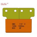
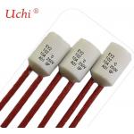
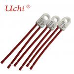
Home Electrical Appliances Thermal Link GP 115C 3A 250Vac Tinned Copper 70mm
|
|
Home Electrical Appliances Thermal-link Radial Shape GP C3 115 °C 3 A 250 Vac,Tinned Copper Wire, Total Length 70mm
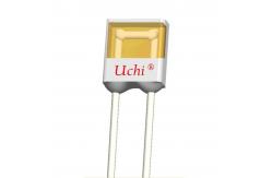
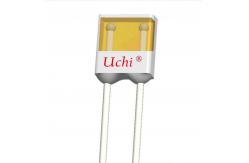
Alloy Thermal-link / Thermal Cutoff (TCO) is defined as a
non-resettable protective device functioning one time only. It is
wide- ly used in electrical equipment. Alloy TCO is mainly consist of
fusible alloy, flux, plastic or ceramic case, sealant epoxy and lead wires. Normally, fusible alloy is jointed to the two lead
wires. Under abnormal conditions, when the temp. reaches to the fusing temp. of alloy TCO, the fusible alloy melts and quickly
retracts to the two lead wire ends with the aid of the flux and
dis- connects the circuit completely. Rated Current 1 A to 200 A, Rated
Functioning Temp. 76 °Cto 230 °C, with CCC, UL, CUL, TUV, KTL, PSE, Approvals and RoHS, REACH compliant.
Thermal-link Attention The surface temp.of TCO less than the holding temp of TCO The seal or body of TCO must not be burned or over heated. Installationpositionofmechanicalperformancerequirements Do not locate the TCO in a place where severe vibration always
occurs. Ensure that the lead wire is long enough, and avoid actions such as
press, tensile or twist. The seal or body of TCO must not be damaged. Soldering Hand Soldering Soldering should be carried out according to table 1 & table 2 The thermal element of TCO is fusible alloy with low melting point,
which is jointed with TCO lead wires. Improper soldering operation (too high soldering temp. , too long soldering time, too
short lead wire etc.) may transfer more heat to the thermal element and TCO may open in advance. When soldering conditions are more severe than those listed in
table 1 & table 2, a heat sink fixture should be used be- tween soldering point and TCO body. When soldering, please do not pull / push or twist TCO body or lead
wires. After soldering, let it naturally cool for longer than 20 s. During
cooling, never move the TCO body or lead wires. Soldering
Soldering should be carried out under the soldering conditions listed in table 2. Table 2 Soldering Time (s)
Wave Soldering The wave soldering parameters as table 3, For reference only, when
TCO is for practice use, you need to do some validation experiments. For example, using X-RAY to see the fusible alloy of TCO whether damage after wave soldering. Mechanical Connection Riveting
Suitable for the lead wire diameter (d) of TCO ≥1.2 mm . Choose small resistivity riveting material and be riveted.
A flexible lead or lead with low resistance should be used to rivet the TCO. Contact resistance should be minimal, Large contact resistance will lead to higher temp., TCO Functioning in advance
Crimping
Suitable for the lead wire of TCO is flat electrode. Choose small resistivity crimping material and be riveted. Crimping process, to ensure that the lead will not be reversed, sealing resin will not be destroyed. Contact resistance should be minimal, Large contact resistance will lead to higher temp., TCO Functioning in advance.
Please see the specification |
|||||||||||||||||||||||||||||||||||||||||||||||||||||||||||||||||||||
| Product Tags: TUV Thermal Link 250Vac Thermal Link 70mm Thermal Fuse | |||||||||||||||||||||||||||||||||||||||||||||||||||||||||||||||||||||
|
Home Electrical Appliances Thermal Link GP 115C 3A 250Vac Tinned Copper 70mm |
|
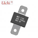
Batteries Automobile Electronic 100A 150A 200A Alloy Thermal Link Thermal Cutoff Tco |
|
40A Alloy Thermal Link for Batteries Automobile Electronic Thermal Cutoff TCO |
|
Home Electrical Appliances Transformers 10A 16A Alloy Thermal Link Tf 102C |
|
10A 16A 20A Alloy Thermal Link Home Electrical Appliances Transformers Tf 102C |

|
Transformers Tf 102C Fusing Temp 99C Alloy Thermal Link Home Electrical Appliances |