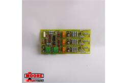
GE DS200LPPAG1A Line Protection Board
|
|
Product Specification
Product Details Features 7 jumpers and 2 terminal blocks with 3 terminals on each. The jumpers are identified as JP1 through JP7. The GE Line Protection Board DS200LPPAG1A also contains test points. The board is installed on standoffs on another component of the drive. The signal wires that connect to the board originate on the other component. Disconnect any cables that are connected to the board, including the signal wires connected to the terminals. Note where the signal wires are connected on the terminal blocks. This will make the installation of the replacement board faster and reduces the opportunity for mistakes in connecting the terminals. It is best practice to remove the component the board is attached to together as one piece from the drive. Refer to the information that describes the installation of the other component to understand the steps to removing it. Then remove it from the drive and place it on an EDS protective surface, for example a flattened out static bag.
GE News GE-led Consortium to Build Two High-Efficiency, Lower Emission HA Combined Cycle Power Units at Dolna Odra Power Plant in Poland: PGE’s Dolna Odra Plant will be equipped with two GE 9HA.01 gas turbines, two steam turbines, two generators and two heat recovery steam generators to deliver world-class efficiency and flexibility for the combined cycle power plant.
More Products
Contact Us |
||||||||||||||||||||||||||||||||||||||||||||
| Product Tags: general electric board ge multilin relays |