
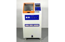
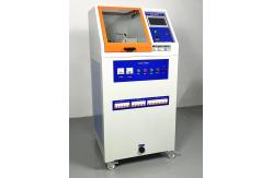
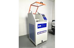
Oxygen Environment IEC 60601-1 Spark Ignition Tester For Me Equipment / Systems
|
|
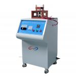
IEC 60601-1 Spark Ignition Tester to check the RISK of fire in an OXYGEN RICH ENVIRONMENT for ME EQUIPMENT & ME SYSTEMS 1.According to standard: IEC 60601-1-Figure 34-figure37(clause 11.2.2) 2.Specifications
11.2.2 M E EQUIPMENT and ME SYSTEMS used in conjunction with OXYGEN RICH ENVIRONMENT 11.2.2.1 RISK of fire in an OXYGEN RICH ENVIRONMENT a) * A source of ignition is considered to exist in an OXYGEN RICH
ENVIRONMENT when any of the following conditions exist in NORMAL
CONDITION and SINGLE FAULT CONDITIONS (including voltage and
current): Items 4) and 5) address the worst case where the atmosphere is 1 00
% oxygen, the contact material (for item 5) is solder and the fuel
is cotton. Available fuels and oxygen concentrations should be
taken into consideration when applying these specific requirements.
Where deviations from these worst case limits are made (based on
lower oxygen concentrations or less flammable fuels) they shall be
justified and documented in First, the place(s) within the ME EQUIPMENT where sparking might
cause ignition are identified. Then the material(s) of the parts
between which sparks can occur is identified. Two contact pins made of the material to be considered are placed
in opposition (see Figure 34). One pin has a diameter of 1 mm, the
other of 3 mm. The electrical source is connected to the pins as
shown in Figure 35 to Figure 37. A piece of cotton is placed close
to the contact surfaces of the two pins. The contacts are
constantly flushed by oxygen with a speed of less than 0,5 m/s via
a tube. The cathode is moved to the anode to close the contacts and
pulled back to open them again. A minimum of 300 trials has to be
performed before it can be decided that the sparks do not ignite.
If the sparks get smaller because of bad surfaces of the
electrodes, the electrodes are cleaned with a file. If the cotton
gets The situation with the highest voltage or current respectively and no ignition defines the upper limit. A safe upper limit is given by dividing the upper limit of voltage or current respectively with the safety margin factor of three. Figure 34 – Spark ignition test apparatus Figure 35 – Maximum allowable current I as a function of the maximum allowable voltage U measured in a purely resistive circuit in an OXYGEN RICH ENVIRONMENT Figure 36 – Maximum allowable voltage U as a function of the capacitance C measured in a capacitive circuit used in an OXYGEN RICH ENVIRONMENT Figure 37 – Maximum allowable current I as a function of the inductance L measured in an inductive circuit in an OXYGEN RICH ENVIRONMENT |
||||||||||||||||
| Product Tags: Oxygen Environment Spark Ignition Tester IEC 60601-1 Spark Ignition Tester 50HZ Electrical Safety Test Equipment |

|
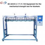
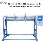
25° Horizontal Angle Blankets Mechanical Strength Test Apparatus IEC60335-2-17 Figure BB.1 To BB.3 for Blanket Evaluation |
|
Testing Blankets Mechanical Strength Test Apparatus IEC60335-2-17 Figure BB.1 To BB.3 with 33rpm/min Driving Sprocket Speed |
|
IEC 60335-2-17 Blanket Spark Ignition Test Apparatus for Professional Testing |
|
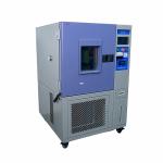
IEC 60335-2-40 Annex NN Flame Arrest Enclosure Verification Test For A2L Refrigerants |

|
Blankets Mechanical Strength Test Apparatus IEC60335-2-17 Figure BB.1 To BB.3 |
|
IEC 60335-2-17 21.103 Equipment For The Mechanical Strength Test For Blankets |