
ANSI/AAMI EC12:2000(R2005) Disposable ECG Electrode Performance Tester
|
Detailed Product Description
|
ANSI/AAMI EC12:2000(R2005) Disposable ECG Electrode Performance
Tester Notes
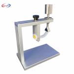
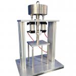
Brief Introduction This equipment is a specialized equipment for electrode integrated
performance testing, designed under the Test Method of disposable
ECG electrode ANSI/AAMI EC12:2000(R2005) Disposable ECG electrodes>. Its main characteristics are built-in standard test program
that can automatically complete the performance tests of the
electrode with one button; built-in test circuit without additional
tooling; automatically produce data results. The following test procedures are built-in for this equipment:
Performance parameters Table 3.1 Performance parameters
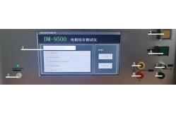
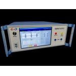
Instrument introduction. ① Touch display: functional display area, touch can achieve all
functional human-machine interaction. ② power switch button: press the instrument to power on ③ Defibrillation control button: During the defibrillation overload
recovery test, press this button to start the test ④ Start / Stop Button: At the test interface, press this button to
control the start and stop of the test ⑤ protective grounding end: for connecting the shield metal
housing.When making weak signal measurement such as noise, if the
environmental noise is found large, the D UT can be protected with
a metal shield and the shield connected to the ground, allowing the
limited shielding of external electromagnetic radiation. Positive pole of ⑥ output: Current output positive pole terminal. Negative pole of ⑦ output: current output negative terminal
terminal. ⑧ voltage measurement end: the terminal used for measuring the
voltage Operation method
Figure 5.1.1
The Main Software Page l. Default enters the main page after the instrument is turned on
The model and name of the instrument are displayed at the top, the
basic function of the instrument on the lower left, and the
advanced options on the lower right 2. Tests for different items can be selected directly through the
directory at the lower left To system the device or calibration,
you can enter the setup interface by clicking the bottom right Typical test circuit Voltage measuring end
Figure 5.1.2 Test the circuit
Figure 5.2 The AC Impedance Test Page. l The AC impedance test page mainly sets the current source and
voltmeter parameters for the test, and displays the measured AC
impedance and peak value voltage. You can also choose whether to
record or empty the data, and control the start and stop of the
test. 2 The AC impedance of the cardiac electrode reflects the ability to
prevent the current from flowing through the electrode interface
and the electrode interface. 3 The impedance of a pair of glue to glue connections can be
determined by applying a sinusoidal wave current with a known
amplitude and observing the voltage amplitude of the electrode to
both ends The magnitude of the impedance is the ratio of the
voltage to the current The peak value of the applied current shall
not exceed 100u A.
Figure 5.3 The DC imbalance voltage test page. l The DC imbalance voltage test page mainly sets the current source
and voltmeter parameters for the test, and displays the test time
and measured voltage. You can also choose whether to record or
empty the data, and control the start and stop of the test 2 The DC imbalance voltage is a voltage formed between the adhesive
bonding electrode pairs due to a different electrode semi-battery
potential. 3 The test instrument is applied to the bias current of the test
electrode no more than 10nA, and is measured by the voltmeter at
the ends after 1min and 1.5min. The abnormal voltage shall be no
greater than 100mV..
Figure 5.4 Composite disorder instability and internal noise test
page. l The composite disorder instability and internal noise test page
mainly sets the voltmeter parameters for the test, and displays the
test time and measured peak voltage. You can also choose whether to
record or empty the data, and control the start and stop of the
test. 2 The voltage generated by a pair of glue-connected electrode pairs
at 1min under a frequency band of 0.15Hz ~100H z is directly
measured by a voltmeter. The peak voltage of subsequent 5min shall
not exceed 150u V..
Figure 5.5 The Defibrillation Overload Recovery test page l The defibrillation overload recovery test page mainly sets the
defibrillation voltmeter, ammeter and voltmeter parameters for the
test, and displays the test time, measured voltage and measured AC
impedance. Data in the test is recorded automatically recorded, you
can choose whether to record or empty data, and control the start
and stop of the test. 2 The defibrillation overload recovery experiment reflects the
ability of the electrode to reduce its existing voltage and restore
the ECG description after defibrillation. 3 Press the defibrillation control button and start the key
instrument to start the test, and the test results are
automatically displayed on the page. 4 The 10 uF capacitor charged to 200V is discharged through a
series circuit of the electrode to 100 Ω resistance, the absolute
value of the polarization electric potential of the electrode pair
after the capacitor starts discharge does not exceed 100m V. within
then 30s and the rate of change of the remaining polarization
electric potential is not greater than ± 1m V/s. After the above
experiment, the 10Hz AC impedance of the electrode pair shall be no
greater than 3kΩ.
Figure 5.6 Offset current tolerance test page l The bias current tolerance test page mainly sets the current
source and voltmeter parameters for the test, and displays the test
time and measured voltage. You can also choose whether to record or
empty the data, and control the start and stop of the test. You can
also choose whether to record the data automatically. 2 This test verifies the compatibility of the electrode with the
200nA bias current allowed by the cardiac monitor. 3 A 200n A DC current is applied to a pair of adhesive electrodes,
which monitors a voltmeter at both ends. The change in voltage on
the electrode is measured at least once an hour. 4 The voltage variation of the electrodes observed over the entire
duration shall not be greater than 100mV. The duration is the
electrode clinical usage recommended by the manufacturer and in no
case shall it be less than 8h.
Figure 5.7 Measurement and calibration page l The operation of the defibrillation power supply will output a
high voltage of 200V, which may damage the voltage measurement
channel, so only used by after-sales personnel of the manufacturer. 2 Defibrillation voltage measurement method:
n The positive and negative output of the instrument are connected
to the positive and negative poles of the oscilloscope probe,
without the load. n Set the defibrillation voltage of 200 V, and start the
defibrillation test.
l Measurement method of the current source:
The appropriate voltage is input at the voltage measuring end, the
input voltage value is measured in three gears of the voltmeter,
and compares the test value relative to the actual voltage value to
determine the accuracy of the voltmeter. Common faults and troubleshooting
|
||||||||||||||||||||||||||||||||||||||||||||||||||||||||||||||||||||||||||||||||||||||||||||
| Product Tags: ECG Electrode Performance Tester lectrode Performance Tester Instrument 220V 50H Electrode Performance Tester | ||||||||||||||||||||||||||||||||||||||||||||||||||||||||||||||||||||||||||||||||||||||||||||
Related Products
|
ISO 5364 -Annex C Medical Test Equipment ISO 5364 Test method for patency of lumen |
|
ISO 5364 Apparatus For Testing Resistance To Collapse Of The Buccal Portion |
|
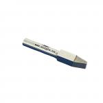
IEC 61010-2-012-Figure 103 Scratching Tool Hard-soldered carbide tip K10 Material |
|
Electrosurgery Analyzer Essential Medical Test Equipment for Accurate and Power Voltage and Current Analysis |
|
Medical Test Equipment for IEC Residual Voltage Testing Includes Cables and Calibration Certificate |

|
IEC 60601-2-2 Testing device for neutral electrodes |
Email to this supplier