
Schneider 4 Slot Backplane 140XBP00400 Modicon Quantum Screw For I/O Modules
|


|
Schneider 4-Slot Backplane 140XBP00400 Modicon Quantum By screw For I/O modules
Specifications Main range of product Modicon Quantum automation platform product or component type Racks backplanes product specific application For distributed I/O modules For local I/O modules For remote I/O modules Complementary free slots 4 mounting support Mounting plate fixing mode By screw net weight 0.45 kg Packing Units Unit Type of Package 1 PCE Package 1 Length 29.5 cm Number of Units in Package 1 1 Package 2 Width 40.0 cm Package 2 Height 30.0 cm Package 2 Weight 4.675 kg Package 1 Width 28.5 cm Package 1 Height 5.0 cm Package 1 Weigh 935.0 g Number of Units in Package 25 Unit Type of Package 2 S04 Package 2 Length 60.0 cm Contractual warranty 18 months Warranty
This page is for all pieces used to compile the Schneider Electric / Telemecanique / Square D Modicon Quantum System. Within a quantum system, the different panels attached to the backplane handle all module addressing and configurations. These systems do not use any DIP switching or any other types of hardware settings. In a Quantum System, there is no specific slot assignments, any module may be used in any slot. There are several types of modules used in the Quantum System, including the Quantum I / O communication Module, the Quantum Modbus Plus Network Option Module, the Modicon Quantum Power Supply, and the Quantum Automation CPU. When combined together on a backplane, these units form a complete Quantum System. Main business: Power Products:Power products are an important part of transmission
and distribution projects.ABB has a worldwide presence in the
manufacture of transformers, switches, circuit breakers, cables and
auxiliary equipment.
OTHER SUPERIOR PRODUCTS
Contact person: Anna E-mail: wisdomlongkeji@163.com Cellphone: +0086-13534205279 Similar Products 140EHC10500C 140EHC20200 140EHC20200C 140ERT85400 140ERT85410 140ESI06200 140ESI06210 140ESI06210C 140HLI34000 140HLI34000C 140MMB10200 140MMB10400 140MMD10200 140MMD10400 140MSB10100 140MSC10100 140MSX10100 140NHP81100 140NOA61100 140NOA61110 140NOE21100 140NOE21100C 140NOE25100 140NOE25100C 140NOE31100 140NOE31100C 140NOE35100 140NOE35100C 140NOE51100 140NOE51100C 140NOE55100 140NOE55100C 140NOL91100 140NOL91110 140NOL91120 140NOM21100
The information provided in this documentation contains general descriptions and/or technical characteristics of the performance of the products contained herein. This documentation is not intended as a substitute for and is not to be used for determining suitability or reliability of these products for specific user applications. It is the duty of any such user or integrator to perform the appropriate and complete risk analysis, evaluation and testing of the products with respect to the relevant specific application or use thereof. Neither Schneider Electric nor any of its affiliates or subsidiaries shall be responsible or liable for misuse of the information contained herein. If you have any suggestions for improvements or amendments or have found errors in this publication, please notify us. No part of this document may be reproduced in any form or by any means, electronic or mechanical, including photocopying, without express written permission of Schneider Electric.
All pertinent state, regional, and local safety regulations must be observed when installing and using this product. For reasons of safety and to help ensure compliance with documented system data, only the manufacturer should perform repairs to components.
When devices are used for applications with technical safety requirements, the relevant instructions must be followed.
Failure to use Schneider Electric software or approved software with our hardware products may result in injury, harm, or improper operating results. Failure to observe this information can result in injury or equipment damage. © 2012 Schneider Electric. All rights reserved.
NOTICE Read these instructions carefully, and look at the equipment to become familiar with the device before trying to install, operate, or maintain it. The following special messages may appear throughout this documentation or on the equipment to warn of potential hazards or to call attention to information that clarifies or simplifies a procedure.
Overview This chapter will give you general information to understand where and when you can use the 140 NRP 954 0• fiber optic repeater modules. The 140 NRP 954 0• fiber optic repeater modules can be inserted in a RIO network. There are 2 models of fiber optic repeaters each supporting one type of fiber optic cables: 140 NRP 954 00 supports multimode optical fiber cable. 140 NRP 954 01C supports single-mode optical fiber cable.
RIO Networks Modicon Quantum RIO network is a high speed (1.544 Mbit/s) local area network (LAN) using coaxial cables. The RIO network supports communication between a PLC and one or more drops of I/O modules dispersed throughout the local area, e.g., the manufacturing or processing facility. There are many possible native topologies that may be used for RIO networks: Linear cable topologies (see the Remote I/O Cable System Planning and Installation Guide for information about RIO coaxial cable networks.): Standard single-cable RIO cable systems Redundant RIO cable systems Dual cable systems Hot Standby cable topologies (see the Modicon Quantum Hot standby System User Manual for information about Hot Standby coaxial cable networks.): Single-cable Hot Standby system Redundant Hot Standby cable system The fundamental architecture of a RIO cable system is as follows: the RIO processor is called the head the network is made of one (linear) or two (dual or redundant) trunk cable(s) Taps are installed along the length of the trunk cable(s), and a drop cable runs from a tap to a drop adapter. A proper impedance match is maintained across the network with 75 Ω trunk terminators.
The following figure shows the basis of a standard single-cable RIO system:
The part number table (see page 22) gives references for the basic components that may be used in a RIO topology.
140 NRP 954 0• Fiber Optic Repeaters Insertion
Insertion of Fiber Optic Repeaters in a Drop Cable The following figure shows a RIO network with the second RIO drop connected to the trunk cable using a long drop cable:
To avoid attenuation, noise and/or distant ground in case of a long drop cable, it can be useful to install fiber optic repeaters.
Application Example The following example will show you the architecture of a highly diagnosed rack inserted in a redundant bus topology and power supplies (AC and DC). This architecture allows to warn and interpret remotely which availability has been lost (power supply, fiber optic cable...):
1 Trunk cable
|
||||||||
| Product Tags: 4 Slot Backplane Schneider Backplane 140XBP00400 I O Modules Backplane |
|
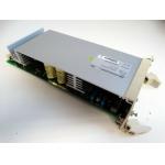
3BSE000863R0001 SR511 POWER REGULATOR MODULE 310 W MAX 35 AMP 18-30 VDC INPUT 5 VDC OUTPUT |
|
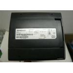
Honeywell TK-FXX102 Redundant Power Supply Module 10SLOT Coated 5.1VDC - 24VDC |

|
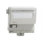
Honeywell TC-ODJ161 Output Module Isolated Discrete 16 Point 24 VDC |
|
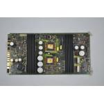
EMERSON FISHER ROSEMOUNT 01984-1137-0001 POWER SUPPLY I/O PCB BOARD MODULE |
|
AO801 Analog Input Output Module 3BSE020514R1 ABB 20mA 12 Bit RLmax 850 Ohm |

|
ABB AC 800F TK808F Supply Cable 3BDM000211R1 115/230 VAC Euro Plug 2 M |