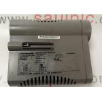
GE FANUC IC697CGR935 , One Slot Controlle Module , Single Slot CPU
|
GE FANUC IC697CGR935 , One Slot Controlle Module , Single Slot CPUProduct Description
Installation of the IC97CGR935 module should not be attempted without referring to the appropriate Programmable Controller Installation and Hot Standby CPU Redundancy Manual. The battery should be connected to one of the module’s battery connectors. The key switch should be positioned to MEMORY PROTECT OFF, and there should be no rack power. Once module is installed in slot 1 of rack 0, power is turned on. The top LED should blink indicating that the IC697CGR935 module is powered up. Once the diagnostic is finished effectively, the top left LED stays on while the second and third LED will be off. The MEMORY PROTECT LED which is the fourth LED, is off because the key switch is in off position. Programming is now ready for the CPU. The CPU can be programmed regardless of the placement of the key. Once the program has been confirmed, the toggle switch can be positioned in the appropriate operational mode. Technical Specifications
Technical InformationSpecifications
|
||||||||||||||||||||||
| Product Tags: 24v DC Negative Logic Output Module PLCs Digital Servo Module 5V DC Digital I O Module |

|
ABB INNPM12 NETWORK PROCESSOR MODULE DCS Module +5VDC 10W MAX |

|
KJ3002X1-BA1 INPUT MODULE 8 CHANNEL 4-20 MA HART BUS POWER 12 V |

|
DI801 3BSE020508R1 INPUT MODULE DIGITAL 24 VDC 16 CHANNEL PLC Module |

|
ABB NTCL01 INFI-Net Communication Link TU Module Termination Unit |

|
Honeywell 51400955-100 Processor Control Board Multi Input Output Network Interface Board |

|
Honeywell CC-PAIX01 Analog Input Module 51405038-275 100MA 24VDC |


