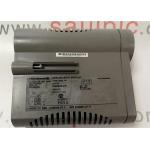
GE FANUC IC693MDL752 5/24v DC TTL Negative Logic Output Module
|
GE FANUC IC693MDL752 , 5/24-volt DC (TTL) Negative Logic Output moduleProduct DescriptionThe 5/24-volt DC (TTL) Negative Logic Output module, IC693MDL752, has 32 negative logic or sinking type output points (active low) and uses 32 bits of discrete %Q output data. The outputs are arranged in four separate groups (labeled A to D), each group comprised of eight outputs each (numbered 1 to 8) with each group having its unique common. It can be installed in any Series 90-30 Programmable Logic Controller (PLC) system having a 5 or 10- I/O slot baseplate. Each group common has user I/O connectors which carry two pins. Each pin on these connectors has a current handling capacity of 3 amperes. Making connections to both pins is recommended when connecting the common, but required for applications requiring high current such as between 3 and 4 amperes. The IC693MDL752 operates in two modes: Transistor-Transistor Logic (TTL) and 12/24V modes. In the TTL mode, each output can switch user loads across +5 VDC. In 12/24V mode, user loads can be switched in the range of +12 to -24 VDC. Also, output points, in each mode (TTL and 12/24V), can sink a maximum current of 25 mA and 0.5A per point respectively. Each output group in the module (A to D) can be utilized in the operating mode that is appropriate for the load requirements of a specific task or application. Group A can be applied to TTL load tasks and Group B to 12 VDC loads, while the Groups C and D can be applied to 24 VDC load tasks. However, when mixing modes (TTL and inductive-type loads), as in this regard, it is important to take cognizance of electrical noise and its effects. User load devices are connected to the module through two male 24-pin connectors that are located on the front of the module. The connectors on the right interfaces with groups A and B output points while those on the left interfaces with groups C and D output points. Optocouplers on the module provide backplane isolation between the field side and logic side. The module also has LED indicators, labeled correspondingly to each output, at the top of the module which indicates the active (ON) or inactive (OFF) status of each output point. There is no reporting of special fault or alarm diagnostics. Each output point has an internal pull-up resistor. When the output point's field-effect transistor (FET) is off, the resistor aims at providing a high logic level for TTL tasks. It does this by pulling up the output to the positive side of the user power input, which, for TTL tasks, is typically +5V. Stopping the CPU forces all 32 output points off and the user must provide power to supply current to the loads. A minimum amount of the user-supplied power is used by the module to provide gate drive to output devices. Technical Specifications
Technical InformationSpecifications
|
||||||||||||||||||||||||||
| Product Tags: 24v DC Negative Logic Output Module TTL Negative Logic Output Module GE FANUC IC693MDL752 |

|
ABB INNPM12 NETWORK PROCESSOR MODULE DCS Module +5VDC 10W MAX |

|
KJ3002X1-BA1 INPUT MODULE 8 CHANNEL 4-20 MA HART BUS POWER 12 V |

|
DI801 3BSE020508R1 INPUT MODULE DIGITAL 24 VDC 16 CHANNEL PLC Module |

|
ABB NTCL01 INFI-Net Communication Link TU Module Termination Unit |

|
Honeywell 51400955-100 Processor Control Board Multi Input Output Network Interface Board |

|
Honeywell CC-PAIX01 Analog Input Module 51405038-275 100MA 24VDC |


