
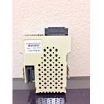
Yaskawa Industrial Servo Drives SGDR-SDA950A01B-EY35 Servopack PWM Amplifier Interface Module
|


Detailed Product Description
|
Industrial Servo Drives Yaskawa SGDR-SDA950A01B-EY35 Servopack PWM Amplifier Interface Module
Quick Details Brand Name:Yaskawa Model Number: SGDR-SDA950A01B-EY35 Manufacturer: Yaskawa Product number: SGDR-SDA950A01B-EY35 Vendor number: 157888-1 Description: SGDR-SDA950A01B-EY35 is an Drives-AC Servo manufactured by Yaskawa Place of Origin:Japan Efficiency:IE 1
9 Similar Products SGDR-SDA140A01BY22 SGDR-SDA950A01B SGDR-SDA0601B SGDR-SDA140A01B SGDR-SDA350A01BY23 SGDR-SDA710A01B SGDR-SDA140A01B SGDR-SDA350A01B SGDR-SDA950A01B-EY35 SGDR-SDA950A01B-EY36 SGDR-SDA950A01B-E SDA3SDA01B SGDR-SDA710A01BY29 SGMPH-02A2A-YR12 SGMPH-01A2A-YR12 SGMPH-02A1A-YR32 SGMPH-02A2A-YR12 SGMAH-04AAA21 SGMD-40AWA-YR13 Test Apparatus The tests were performed using the rig shown in Figure 2 which consisted of a rigid steering wheel connected to a shaft supported by 3 radial bearings. The shaft incorporates a lever arm which is connected to an electrodynamic shaker unit by means of a stinger rod. All mechanical components (i.esteering wheel, shaft, bench) were modeled using the finite element method and were found rigid to frequencies in excess of 300 Hz. The seat, guide-rail and the bench geometric dimensions (see Table 1) were chosen based on average data from European B-segment automobiles. Seat horizontal travel and back-rest inclination were fully adjustable. Geometric Parameter Value Steering column angle with respect to floor 23° Steering wheel hub centre height above floor 710 mm Seat H point height from floor 275 mm Horizontal distance from H point to steering wheel hub centre 390 – 450 mm Steering wheel handle diameter 12.5 mm Steering wheel diameter 325 mm Natural Frequency of the test bench 310 Hz. The steering wheel was vibrated by means of a G&W V20
electrodynamic shaker driven by PA 100 amplifier [8], using the internal sine wave generator. The acceleration obtained at the steering wheel was measured using an Entran EGAS-FS-25 accelerometer located on the top left side of the steering wheel. The accelerometer signal was amplified by means of an Entran MSC6 signal-conditioning unit [6] and monitored by Tektronix TDS210 digital oscilloscope OTHER SUPERIOR PRODUCTS Yasakawa Motor, Driver SG- Mitsubishi Motor HC-,HA- Westinghouse Modules 1C-,5X- Emerson VE-,KJ- Honeywell TC-,TK- Fanuc motor A0- Rosemount transmitter 3051- Yokogawa transmitter EJA- Contact person: Anna E-mail: wisdomlongkeji@163.com Cellphone: +0086-1353420527 Three equal sensation tests; namely test 1, test 2 and test 3 were performed at different frequency and amplitude values. The selection of test frequencies and amplitudes was based on the analysis of steering wheel vibration levels obtained from tests of a Renault automobile on 7 road surfaces using 175/65 R14 and 225/45 R16 tyres driven at 45 m.p.h. [21]. An annoyance threshold test was also performed to measure the maximum level of steering wheel vibration that the subjects were willing to withstand for 10 seconds of exposure time. The frequency range of interest was chosen to be from 5Hz to 315 Hz, using the center frequencies of the 1/3 octave band scale. The reference frequencies for equal sensation test 2 and 3 were chosen at 0.2 and 0.4 ms-2 r.m.s respectively, both at 10 Hz. However, due to the limitation ofthe shaker, equal sensation test 1 was performed with reference amplitude of 0.5 ms-2 r.m.s at 40 Hz. Table 3 summarizes the reference frequencies and amplitude levels. A variation of the method of constant stimuli [4, 9] was used for
the equal sensation tests. A reference vibration stimuli was used for generating each of the three equal sensation curves. The three reference stimuli were 0.5 ms-2 r.m.s at 40 Hz, 0.2 ms-2 r.m.s at 10 Hz and 0.4 ms-2 r.m.s at 10 Hz. Each reference stimuli was presented to the test subjects for 20 seconds, then the frequency of the stimulus was changed and the subjects were asked to give verbal instructions so as to adjust the amplitude of the new stimuli until it produced a similar sensation to the reference. During each test, the subject was required to compare the test signal to the reference within a 30 second time interval so as to remain within human short term memory [1]. All 1/3 octave band frequencies in the range from 5 Hz to 315 Hz (i.e 5, 10, 12.5, 16, 20, 25, 31.5, 40, 50, 63, 80, 100, 125, 160, 200, 250 and 315 Hz) were tested. Since human judgement has been shown to be relative rather than absolute [4 ], stimuli comparisons were limited to occur between frequencies which were no more than one full octave (i.e doubling of frequency) apart.
|
| Product Tags: ac servo pack ac servo drive |
Related Products

|
MR-S12-80A-Z33 MITSUBISHI Servo Drive AMP AC 2 Axis Option Card RF 322 |

|
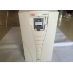
ACH550-01-031A-4 ABB AC Hvac Drive 550 Series IEC Installation Setup 380-480 VAC |

|
3G3JX-A4004 OMRON JX Frequency Inverters AC Drive 1/2HP 480V 0.4KW 3PH |
|
EMERSON SM-ETHERNET ETHERNET MODULE RJ45 CONNECTIVITY Drive Interface |
|
ABB Inverter Standard AC Drive ACS-550-01-059A-4 380-400V 30kw 59A Low Voltage Drives |

|
A20B-0007-0040/04A PC BOARD DI/DO BOARD I/O RELAY CARD 6T/M CONTROL CNC |
Email to this supplier