
Diode Redundancy Module IC200MDL940 Output Relay Isolated 2A FORM A 16PT
|


|
Redundant Power Supply Module GE Fanuc IC200MDL940 OUTPUT RELAY ISOLATED 2A FORM A 16PT
Module Characteristics Points IC200MDL930: 8 individually isolated Form A relay outputs Isolation: Thermal derating None
Output Characteristics Output voltage 0 to 125VDC, 5/24/125VDC nominal
Similar Products IC3600EPSX1 12V LAMP REGULATOR IC3600EPSX IC3600EPSY1 REGULATOR BOARD IC3600EPSY IC3600EPZU1 POWER SUPPLY CARD IC3600KHDA2 RELAY BOARD IC3600KHDB2 RELAY BOARD IC3600KHDC2 RELAY BOARD IC3600KHVA1 RELAY BOARD IC3600KHVA2 RELAY BOARD IC3600KHVB2 RELAY BOARD IC3600KHVD2 RELAY BOARD IC3600KMRA2 MEDIUM-DUTY-RELAY IC3600KMRA5 MEDIUM DUTY RELAY IC3600KMRA6 MEDIUM-DUTY-RELAY IC3600KMRA9 RELAY IC3600KMRB1 MEDIUM-DUTY-RELAY IC3600KMRB2 RELAY IC3600KMRB3 MEDIUM-DUTY-RELAY IC3600KMRB5 MEDIUM-DUTY-RELAY IC3600KMRB6 RELAY, ALT P/N: L8934 (COMMUNICATIONS INST IC3600KMRB9 RELAY IC3600KMRC1 MEDIUM-DUTY-RELAY IC3600KMRC2 MEDIUM-DUTY-RELAY IC3600KMRC5 RELAY IC3600KMRC6 MEDIUM-DUTY-RELAY-MI IC3600KMRC9 RELAY IC3600KMRCD RELAY IC3600KMRD2 MEDIUM-DUTY-RELAY IC3600KMRD5 MEDUIM DUTY RELAY IC3600KMRD6 MEDIUM DUTY RELAY IC3600KMRD9 MEDIUM-DUTY-RELAY IC3600KMRDD IC3600KMRE2 MEDIUM-DUTY-RELAY IC3600KMRE3 MEDIUM-DUTY-RELAY IC3600KMRE5 MEDIUM-DUTY-RELAY IC3600KMRE6 MEDIUM-DUTY-RELAY IC3600KMRE9 MEDIUM-DUTY-RELAY IC3600KMRF2 MEDIUM-DUTY-RELAY IC3600KMRF5 MEDIUM DUTY RELAY Relay output module IC200MDL930 provides 8 individually-isolated
Form A relay outputs. Relay Output Modules IC200MDL940 (shown below) and BXIOOR162 provide 16 individually-isolated Form A relay outputs. The contact is closed when the host CPU is active and the corresponding output logic bit is “1”. Power for module operation comes from the backplane. Loads must be
powered by an external source. Intelligent processing for this module is performed by the CPU or NIU. LED Indicators Individual green logic-side LEDs indicate the On/Off status of each
output point. The output LEDs are logic-driven and independent of
load conditions. The green OK LED is ON when backplane power is present to the module. Preinstallation Check Carefully inspect all shipping containers for damage. If any
equipment is damaged, notify the delivery service immediately. Save
the damaged shipping container for inspection by the delivery
service. After unpacking the equipment, record all serial numbers. Save the shipping containers and packing material in case it is necessary to transport or ship any part of the system. Installation in Hazardous Locations • EQUIPMENT LABELED WITH REFERENCE TO CLASS I, GROUPS A, B, C &
D, DIV. 2 HAZARDOUS LOCATIONS IS SUITABLE FOR USE IN CLASS I,
DIVISION 2, GROUPS A, B, C, D OR NON-HAZARDOUS LOCATIONS ONLY • WARNING - EXPLOSION HAZARD - SUBSTITUTION OF COMPONENTS MAY IMPAIR SUITABILITY FOR CLASS I, DIVISION 2; • WARNING - EXPLOSION HAZARD - WHEN IN HAZARDOUS LOCATIONS, TURN OFF POWER BEFORE REPLACING OR WIRING MODULES; AND • WARNING - EXPLOSION HAZARD - DO NOT DISCONNECT EQUIPMENT UNLESS POWER HAS BEEN SWITCHED OFF OR THE AREA IS KNOWN TO BE NONHAZARDOUS. For module IC200MDL930, if additional bussed terminals are needed,
the B terminals can be made available by using a shorting bar. The
shorting bar has a maximum current-carrying capacity of 2 Amps per
point. See chapter 2 of the VersaMax I/O System Manual, GFK-1504,
for more information When wiring outputs to inductive loads, use of external suppression circuits is recommended. See chapter 2, “Installing Wiring for I/O Devices-Wiring to Inductive Loads” in the VersaMax I/O System Manual, GFK-1504, for more information. Row B connections are for 16-point modules only. Side B connections are for 16-point modules only. The module’s backplane 5 volt power requirement increases as the
number of points that are simultaneously on increases. The chart
below shows the relationship between the number of points on and
the maximum current required. Operating Note If hot insertion of a module is done improperly, the operation of other modules on the same backplane may be disrupted. See Installing a Module on a Carrier in the VersaMax Modules Manual, GFK-1504.
Contact person: Anna E-mail: wisdomlongkeji@163.com Cellphone: +0086-13534205279 |
||||||||
| Product Tags: analog interface module plc power supply module |
|
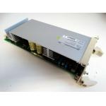
3BSE000863R0001 SR511 POWER REGULATOR MODULE 310 W MAX 35 AMP 18-30 VDC INPUT 5 VDC OUTPUT |
|
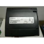
Honeywell TK-FXX102 Redundant Power Supply Module 10SLOT Coated 5.1VDC - 24VDC |

|
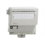
Honeywell TC-ODJ161 Output Module Isolated Discrete 16 Point 24 VDC |
|
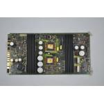
EMERSON FISHER ROSEMOUNT 01984-1137-0001 POWER SUPPLY I/O PCB BOARD MODULE |
|
AO801 Analog Input Output Module 3BSE020514R1 ABB 20mA 12 Bit RLmax 850 Ohm |

|
ABB AC 800F TK808F Supply Cable 3BDM000211R1 115/230 VAC Euro Plug 2 M |