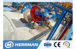
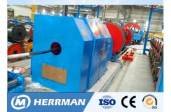
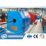
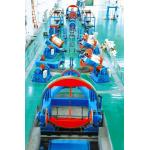
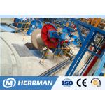
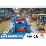
1.Summary 1.1 Application JPD-3150Drum twisting line laying-up used for laying-up of large
section ,long length power cables. The line is for laying-up of
pre-twist or non-twist cable cores. 1.2Composition and summarization The machine is composed of ø2250 rotating pay off stand (6
sets),hydraulic lift platform , wire assembly die , filling yearn
pay off stand (2 sets),guiding stand ,three row die set,non-metal
taping device(2 sets),phase correction ,meter counter,6T rotating
caterpillar device ,ø3150 rotating pay off and traverse
stand,electrical transmission system and pneumatic hydraulic
system. The equipment adopts PLC to command and coordinate the startup,
operation and synchronous rotation of whole machine and each
sectional motors in a unified way. Each frequency-converter motor
is controlled by import inverter. It uses touching screen to show
and adjust operating state of production line and technical
parameter. Electrical control system is advanced, convenient and
reliable. Taping device adopts single motor to drive, taping pitch is
step-less and adjustable. Caterpillar haul-off and rotary take-up
adopt mechanic linkage, synchronous rotation, single motor controls
haul-off line speed and the pitch is step-less and adjustable. Pay-off stand accepts single motor to drag and rotate. It can have
synchronous rotation as rotary take-up stand, and adopts inching
jogging operation as well. Take-up stand uses under roller type
structure to add rigidity to take-up stand; smoothness and
reliability to operation. The line is provided with various protection measures and auto stop
function if there is any fault , easy and reliable operation. 2.Basic technical specification of equipment 2.1 Max outer diameter of finished cables Ф150mm 2.2Max rotating speed of drum twist & pay-off stand 30r/min 2.3 Max linear speed 50m/min(stepless) 2.4 Pitch of finished cable 200~2800mm 2.5 Max power of caterpillar 6T 2.6 Max rotating speed of non-metal taping 840rpm 2.7 Filling yearns specification (OD* ID*Width*QTY) Ф400XФ20X360X10 Ф800XФ52X320X4 2.8 Main motor N=75KW(AC)n=1500rpm 2.9 Caterpillar motor N=45KW(AC)n=1500rpm 2.10 Non-metal taping motor N=15KW(AC)n=1500rpm | | Operation Manual of JPD-3150 Drum Twister | | | 2.11 Rotating pay off stands motor(6 sets) N=22KW(AC)n=1500rpm 2.12 Traverse motor N=2.2KW n=1500rpm 2.13 Take up motor (2sets) N=7.5KW(AC)n=1480rpm 2.14 Pay off reel specification PN2250 2.15 Take up reel specification PN3150 3.Technical specification & structure of each main components 3.1 ø2250 Rotating type pay off stand 3.1.1 Structure specification 3.1.1The structure of the component is fork -stand cantilever
type.It is composed of drive motor, reducer, pneumatic brake
device, fork frame, wire disc clamping mechanism, horizontal bolt,
tension control mechanism and hydraulic lifting platform. This pay off stand use Ac variable frequency motor driver the
fork-stand rotating , Pay-off stand can have synchronous rotation with take-up stand, and
it also can be fixed not to rotate, as well as inching rotation
controlled by people. Pay-off tension of Ф2600 rotary pay-off stand is controlled by
pneumatic, compressed air is sent to rotary fork stand by one
rotary pneumatic junction, then to tension disk by 2 tension
controller.Pay-off tension can be adjusted freely on pneumatic
control cabinet under the state of stopping and operating. Note: rotary pneumatic junctions at the end of the main shaft
should be lubricated during operation, or it will damage the sealed
components inside junctions. Pay-off bobbin clamping is controlled by electricity. It drives
pintles forward and backward by motor through worm pair and nut
screw pair, so as to clamp or release the bobbin. The pay-off stand has one horizontal bolt, which is composed of
bolt and two position switches. It is a kind of protection device.
When fork stand is on the horizontal position, bolt mounted on the
base plate can be plugged into the rounded hole at the end of the
fork stand. One position switch works, meanwhile, the bobbin
clamping device and hydraulic lifting platform can work to finish
the bobbin clamping, relaxing, loading and unloading. At the same
time, main machine cannot start because of interlocking. When
withdrawing the bolt, another position switch works, at the mean
time, main engine can start while bobbin clamping device and
hydraulic lifting platform are locked. 3.1.Technical specification a.Max rotating speed 30r/min b. Max loading weight of pay off stand 8T c. Pay off reel PN2250 | | | | | d. Power of electrical motor N=22KW(AC) e Pay-off tension 10~150da Note: Rotary pay-off stand can not exceed 70% of designed max speed
when in heavy load. 3.2 Three row die holder 3.2.1 Structure specification The compacting die holder is provided with 3 sets of compacting
die.1 set of compacting die is fixed type,and other two sets are
mobile compacting dies.The front or back position of compacting die
can be adjusted. In front of this compacting die is installed with
3 core, 4 core ,5 core or 6 core wire assembly plate to assembly
wire. 3.3Taping device (Non-metallic taping device) 3.3.1 Structure specification Structure of the device is two tape pads and half tangent; the
device mainly consists of guide tape device, rotating support,
braking device, electric control system, shield, etc. Cables can be
overlapped girded by it. Speed of taping head is driven by one unit of 15kw (AC) motor,
working speed and rotating directions can be realized by adjusting
speed and directions of the motor. Width of tapping tape is
15~80mm,diameter of tape pads is Ф600mm and aperture of tape pads
is Ф80mm. Tension of tape pads can be adjusted by mechanical device
between 2.5-15kg. During the working process, invariability can be
ensured by tension feedback device and will not be affected by any
change of tape pad diameter. The taping device is equipped with tape-breaking stop protection.
When tape-breaking occurs or device finishes taping, tape-breaking
stop device will send the stopping signals. After braking device
receives braking signal, electromagnetic valve will start working ,
letting pressed air into mini type air cylinder quickly and pushing
skate brake to hold braking wheel to make rotary body of tapping
head stop rotating immediately, so as to reduce attacks to the
drive medium. Shield of taping head has the function of safety protection. When
its gate opens, position switch will switch off and whole machine
can not start. Whole machine can start only after the gate closes
and the position switch shuts down. 3.3.2Technical specification a.Width of taping 15~80mm b.Tape size Ф600×Ф80mm c. Taping tension 2.5~15kg d. Taping pitch Step -less e . Max rotating speed of taping head 840r/min 3.4 Rotating belt caterpillar 3.4.1 Structure specification | Caterpillar device is composed of front and back support,cylinder
compacting device,caterpillar tension device,caterpillar speed
reducer and rotating air inlet. The box body of the front stand is welded with steel plate, and the
large bearing supports the main shaft.The two ends of the main
shaft have a pair of synchronous belt drive, the right end of the
synchronous belt through the flat key and the main shaft
connection, drive the rotation of the whole body, its transmission
speed ratio with the disc head of the main gearbox is completely
consistent.Thus, the synchronized rotation of crawler traction
rotating body and disc twisting body is guaranteed.The left end
synchronous belt wheel is mounted on the main shaft, and its power
is transferred by a 45kw ac variable frequency motor on the ground
through the synchronous belt, and then finally through the
synchronous belt to the traction reducer, and then the traction
belt driven by the traction wheel, and then drag the cable
forward.The rotation of the rotating body itself will cause an
impact on the speed of the 45KW motor transferred in, resulting in
an original traction line speed of the equipment. The influence of
this speed on the final traction line speed of the equipment can be
corrected by using the electric control of the speed of the 45KW
motor. The rotating pneumatic joint on the main shaft of the rear support
frame provides a working air source for the compression cylinder
and tensioning airbag. Cylinder clamping device, a total of 10 cylinder on both ends of
each cylinder by fluctuation pressure roller, pressure roller
bracket connection between the two pressure roller bracket with a
connecting rod, so that the cylinder and the connecting rod and the
support of a linkage, roll up and down in the process of expansion,
thus ensuring the cylinder pressure roll up and down movement at
the same time, make the crawler traction cable is always on.Crawler
tensioning device is composed of a cylinder and upper and lower
tensioning wheels. The stretching of the cylinder through the
connecting rod makes the upper and lower tensioning wheels relax or
tensioning at the same time, ensuring the tensioning of upper and
lower crawlers.The opening and closing of upper and lower crawler
is completed by the cylinder compaction device and crawler
tensioning device.When to open, first make the tensioning cylinder
action, and then relax the pressure cylinder;When the clamping
cable is to be closed, press the cylinder to press the cable, then
loosen the tension cylinder (when the tension cylinder is relaxed,
this step can be omitted), and finally make the tension cylinder to
tighten the belt.The pressure of the compression cylinder and the
tensioning cylinder can be adjusted separately. Generally, the
pressure of the compression cylinder should be less than that of
the tensioning cylinder. 3.4.2 Technology specification a Max linear speed 50m/min b Max. Pulling force 6000dan c Max OD of passable cable Ф150mm d Max rotating speed 30r/min 3.5 ø3150 rotating take-up stand with traversing 3.5.1 Structure specification The device is composed of drum head, support roller stand,
stranding gearbox and hydraulic lifting platform. | | Operation Manual of JPD-3150 Drum Twister | | | Drum head is the key component of Ф4000 drum twister; it is type of
fork stand supporting wheel. Its main body is composed of fork
stand, traverse device, clamping device, take-up device, pneumatic
brake device and conduction device, etc. a .Fork stand Fork stand is like the skeleton, it has the function of linking,
installing bobbins and other components. b .Traverse device It is composed of one2.2KW AC motor,WHX-06-12.5-I helical gear
reducer, traverse holder, lead screw, and proximity switch, etc.
Changes of traverse pitch can be realized according to that of
rotating speed of AC motor. When pitch is given, rotating speed of
AC motor is changing with that of take-up motor; But, traverse
reversing is realized by position switch. C Support roller stand It is the main loader of drum head. This support roller stand is
single structure. It needs to be adjusted periodically due to
looseness and abrasion of spare part. Specific contents can be
found in “Installation, Maintenance and operation” of the using
manual. D Clamping device Clamping of take-up bobbin is controlled by electricity. It drives
pintles forward and backward by motor through belt transmission
pair, worm pair, and nut screw pair, so as to clamp or release the
bobbin. E Take-up device Take-up device is composed of 2motors, speed reducer device, drive
plate device, speed detection feedback system, etc. Motor drive
device adopts the winding feature of moment motor to guarantee the
certain tension of take-up device all the time. Tension can be
adjusted by changing the electric voltage. f Horizontal bolt g Conduction device The device is composed of carbon brush, brush stand, conduction
copper collar and so on. It serves to supply power and transmission
signal to motor fitted on rotary fork stand and other components. h.Hydraulic lifting platform | | Operation Manual of JPD-3150 Drum Twister | | | Bobbin loading and unloading can be finished by hydraulic lifting
platform. Note: Overflow valve is used to adjust the pressure of oil circuit;
you should never adjust the pressure to an excessive high place.
Usually, adjust it gradually from low level to higher level in
order to work normally (that is, to hold the bobbin) is much
better. There are 2 guide tracks on lifting platform; you should adjust the
width of them according to width of side plate outside bobbin, so
as to make sure that the bobbin is set at center of the platform.
Or, you may destroy the equipment after a long time running. Main
engine can be started unless the lifting platform has been fallen
down to the lowest position. 3.5.2 Technical specification A Max rotating speed 50r/min B Max loading weight 20T C Traverse pitch 200~2800mm D Take up reel size PN3150 E Main motor power N=75KW(AC) F Take up motor power N=7.5KW (2 sets ,AC) G Traverse motor power N=2.2kw(AC) H Clamp motor power N=0.55kw (2sets ,AC) Note;Rotation pay off shouldn’t be more than 70% of max.design
speed. 4.Installation and maintenance 4.1Installation | | Operation Manual of JPD-3150 Drum Twister | | | Installation of this machine should consult size of layout drawing
and foundation drawing of the machine and obey the construction
requirements; finishing drawing the traveling central line and
central line of earth’s axis; determining the structure and
thickness of concrete according to geological conditions and load
capacity of the machine; digging pits, slots, and anchor bolt holes
with different depths; preparing for cement bases. After concrete has already reached to the maintenance term, you can
draw ink lines of cables traveling central line, central lines of
both earth shaft and installation on the terrace. At last, put
every component in their right places. Set main shaft center of
central rotary pay-off stand as a point and main shaft center of
drum head stranding gearbox as another point. Then you can use
steel wire (diameter is Φ1mm) to joint the two points together as a
line .You can use turn buckle to pull it tight, and use heavy punch
to make the small steel wire to stand in the same vertical face
with ink line on the terrace. Together you can adopt a level
instrument to calibrate central height mark of steel wire to be 1
meter. Then, you could adjust central height of all components
according to it. Note: Attentions must be paid to that the
circumferential gap of blind flange which was one end close to
conduction device of main shaft of fork and stranding gearbox
should be equivalent. It can be realized by adjusting devices of
supporting wheel device. First make horizontal alignment of central
height of fork stand. Then, with fork stand as the benchmark to
adjust horizon of stranding gearbox.Finally, re-examining
completely whether all sizes are equal to the requirements of the
graphic. When correcting horizon and heights of installation, you
must follow the working standard of TJ231.The allowable deviation
of each component is ≤0.5mm.After examination, you are able to
start second grouting. After about two-week’s maintenance, you
should calibrate horizontal, vertical, central heights and sizes of
the whole machine precisely. If any change occurs, it is permitted
to add sizing block to the bottom of the machine, then fasten the
anchor bolt. Wire the connecting line according to the electrical wiring
drawing. Jointing pneumatic and hydraulic pipelines and verifies
the correctness of electric connection, no leakage in both of the
pipelines. After installation and regulation, you ought to clean
out the greasy dirt of every assembly especially the exterior
surface of big bearing wheel and supporting wheel. Then inject the
stated lubricant in lubricating point; checking the fastening
pieces of every component to avoid looseness. Compressed air or
other methods should be used to clean out sundries in every
pneumatic and oil pipe, to prevent the sundries from entering into
pneumatic, hydraulic devices. After injecting hydraulic oil into every hydraulic box, start the
oil pump motor, operate lifting and putting-down the oil cylinder
time after time, making oil cylinder and pipeline full of oil and
then filling the oil box with oil. 4.2 Trial run You should trial run every component one by one. At the beginning,
first check the firmness of them, let bobbin twisting head,
caterpillar-tractor and taping device in free position, and let
stranding gearbox in low-speed step. Start main motor slowly and
gradually rise to max speed step by step. After ten-minute
operation, then reduce the speed and stop the device. Then, let
stranding gearbox rotate at intermediate speed and high speed
respectively. Carry out the above trial run, let drum head rotate
at low speed, intermediate speed and high speed separately and try
for 20 minutes. Add proper quantity of oil to rotary connection of
caterpillar-traction (twisting off inlet connection of rotary
connection individually) to reduce friction force between sealing
ring and distribution connection. Adjusting compacting air pressure
and tension pressure .Then join with caterpillar-traction, taping
device, etc. and has trial run from low speed to high speed. Next step is trial run of rotary pay-off stand then the trial runs
of take-up device and traverse device. During the trial run course, operating progressively form low speed
to higher speed. Before running in high speed, checking fastening
piece once again is suggested. If any abnormal situation appears,
you should stop the machine to check in time. Continue trial run
after clearing of the fault.Set fork stands of drum head and rotary
pay-off stand at horizontal position respectively. And begin test
run of clamping device and hydraulic lifting platform. Start hydraulic system, make lifting platform rise or fall to the
positions which are needed for lifting and putting down bobbins,
and adjust position of each position switch. Note: Overflow valve should be adjusted gradually from low level to
higher level. It is proper for lifting platform to carry the bobbin
filled with cables, and you should never adjust the overflow valve
too low. Power-on pneumatic device, observing touching conditions of every
pneumatic brake block and brake wheel to adjust brake pressure by
pressure regulating valve. Note: braking pressure and pay-off tension should be regulated from
small to bigger level gradually. You should never adjust it to an
excessive level. | | Operation Manual of JPD-3150 Drum Twister | | | After finishing all the above trial run, next you can operate whole
machine linked trial run, dry run for 2 hours from low speed to
higher level. Both of its rotary pay-off stand and drum head should
run for 40 minutes. There must be no abnormal sound. After the
whole process, checking temperate rise of each bearing to make sure
it is below 40℃. Test production can be started unless the dry run
meets the criterion. 4.3 Operation Before formal production, correctness, safety and reliability of
interlocking mechanism of all running components must be checked.
Follow the technology requirements to outfit needed wire mould; to
place bobbins of every pay-off stand; to fix belting reel; to pull
gear change hand level to required steps; to adjust traverse pitch
adjuster knob to suitable place. Install Ф3150 take-up bobbin after
adjusting the right tension of take-up motor according to the wire
width. After bobbins have been fixed onФ2250 rotating pay-off stand,
pay-off tension of each bobbin should be adjusted properly and
uniformly, bobbin must be pulled tightly and the retaining
mechanism should be reliable enough. Letting discharging cable core
wire pass the guiding stand then via assembly die carrier to
assemble them together ,and linked with advanced prepared leading
wire (Leading wire pass through tapping head, caterpillar capstan,
conduction device , stranding gearbox and traverse stand to wind on
the take-up bobbin). Then jogging to start the machine, adjusting
the tapping tension, entrance angle, pitch and traverse pitch, etc.
to suitable level. Machine can be run after wires winding on
take-up bobbin. After cables reach to the required length, stop the machine and jog
to set fork stand to horizontal situation and plug the bolt into
brake wheel, start bridge crane to hold take-up bobbin, power-on
clamping motor. Turn the pulling rod and releasing bobbins, bridge
crane rise to ground; rolling out the bobbin and be installed in
the empty bobbin. Note: After bobbins are clamped by pintles, clamping motor ought to
be closed or it is easily to damage driving mediums like the
clamping motor. Withdraw the horizontal bolt and wind cables around
the empty bobbin. When all these works is done, formal star-up is
allowed.(The course of rotating pay off stand loading and unload is same of the kind mentioned ) Attention: Line-start should be slow. Normal stop should be slow,
the speed should be reduced, too. You must bear this in mind that the fastening situation of spare
parts on rotary bodies like fork stand must be checked frequently
to avoid human injury or equipment accidents caused by spare parts
pull-off. Read the Electrical Using Manual before operation. 4.4 Maintenance After installing and using this equipment for one month, examine
the horizon of drum head and rotary pay-off stand, contact
situation of conduction device, connecting place of related
components and adjust them. Hydraulic system adopts 30# machine
oil; 20# machine oil is injected into oil fog machine. Overall
parts of the equipment generally accept single lubrication, bearing
place, gears and feed screw nut which cannot be used machine oil
are applied with Albany grease. Every surface of them should be
added with machine oil 50# to lubricate. Piston connecting rods of
caterpillar-tractor and clamping cylinder should be painted on 30#
machine oil to protect surface of the piston and reduce the
abrasion of lock ring of front cylinder head. Oil adding and oil
change period should be done regularly. | | Operation Manual of JPD-3150 Drum Twister | | | 4.5 Air supply provided by users should be matched with the
following requirements: 4.5.1 Air pressure: 0.6Mpa 4.5.2 Air amount : 1.0M3/MIN(not include capstan cooling air) 4.5.3 Compressed air should be dry without impurity or dust. 4.6Air and circumstance requirements of electrical control
cabinet:: Temperature ≤45℃ Relative moisture ≤60% 5.List of documents 5.1 Using Manuals (Mechanical & Electrical) 5.2Layout Drawing 5.3Foundation Drawing 5.4Transmission drawing 5.5 Transmission system drawing 5.6 Pneumatic Hydraulic Piping Diagram 5.7 Electrical Schematic Design(main machine) 5.8Electrical Piping Diagram (main machine) 5.9 External System Wiring Diagram(main machine) |
|