HW-HSB-M4-05DM-222X High speed configuration available that allows data rates up to
6.250 Gb/s via 100 ohm matched impedance differential pairs. • Partially populated standard HDB3 mother board and daugher board
bodie Mates with: • High Speed Daughter Board HSB³ HIGH DENSITY CONNECTOR FEATURES: • Polarization: “D” shaped design • Keying: Optional keys offer 36 unique keying combinations • Guide:Pins Optional guide pins provide additional alignment • Radial Misalignment:Capable of correcting up to a 020” initial
radial misalignment • Angular Misalignment:Capable of mating with up to a 2° initial
angular misalignment How to order: | 1 | 2 | 3 | 4 | 5 | 6 | 7 | | | Number of Differential Pairs | Differential Signal | Brush Wire Plating | Termination | Contact Termination Finish | Less Hardware (Purchased separately see pg XX for hardware options) | | HSB-M4 | -03 | D | M | 24 | 2 | X |
1. Connector Type HSB-M4 Designates High Speed HDB3 I/O Connector 2. Number of Contacts Number Differential Pairs | No. Low Speed Signals | Dimension A | Dimension C | | 03 | 20 | 1.375 | 1.075 | | 05 | 30 | 1.725 | 1.425 | | 07 | 40 | 2.075 | 1.775 | | 10 | 60 | 2.775 | 2.475 | | 13 | 80 | 3.475 | 3.175 |
3. Differential Signal 4. Brush Wire Plating | M | 0.000050 Au Min. thick over Nickel | | C | 0.000020 Au Min. thick over Nickel |
5. Termination | | Type | Stickout (Dim. E) | | 22 | PCB, Straight, .016 Dia | 0.120 | | 23 | PCB, Straight, .016 Dia | 0.150 | | 24 | PCB, Straight, .016 Dia | 0.180 | | 26 | PCB, Straight, .016 Dia | 0.240 | | 28 | PCB, Straight, .016 Dia | 0.300 |
6. Contact Termination Finish | 2 | Gold plated in accordance with MIL-G-45204, Type II, .000030 Min.
thick Gold over .000050 Min.thick Nickel | | 5 | Tin plated in accordance with ASTM B545, .00010 Min. thick Matte
Tin over .00010 Min. thick Nickel | | 6 | Tin-Lead plated in accordance with SAE-AMS-P-81728, .00010 Min.
thick Tin-Lead over .00010 Min. thick Copper |
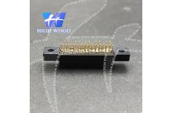
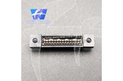
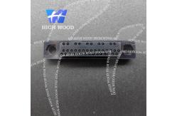
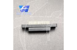
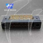
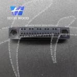
7. Hardware Product pictures: HDB³ & HSB³ HIGH DENSITY CONNECTOR PERFORMANCE: | Durability: | 100,000 mating cycles | | Insertion/Extraction Force: | 1.5 ounce typical per contact | | Operating Temperature: | -65° to 125°C | | Current Rating: | 2 amperes Hot swap 1 ampere maximum (load dependent) | | Insulation Resistance: | 5 gigaohms minimum | Dielectric Withstanding Voltage: | 750 volts, 60 hertz, rms @ Sea Level, 250 volts, 60 hertz,
rms @ 70,000 feet elevation | | Solderability: | MIL-STD-202, Method 208 | | Salt Fog: | 48 Hours IAW MIL-STD-1344, method 1001, test condition B | | Humidity: | IAW MIL-STD-1344, method 1002, type II | | Vibration: | 4 hours in each of 3 mutually perpendicular axes IAW MIL
STD-1344, method 2005, test condition V, letter H | | Shock: | 1 shock along each of three mutually perpendicular axes IAW
MIL-STD-1344, method 2004,test condition G | | Data Rate (HSB3 ): | Capable of up to 6.250 Gbps (consult Amphenol for
arrangement) |
MATERIALS: | Insulator: | Liquid crystal polymer, 30% glass filled | | Contact: | Wire | Beryllium copper per ASTM B197; finish is gold per ASTM B488 over
nickel per AMS-QQ-N-290 | | Holder: | Brass similar to UNS C33500; available finishes include gold per
MIL-G-45204, tin-lead per MIL-P- 81728 or tin per MIL-T-10727 (RoHS
Compliant) | | Sleeve: | Stainless steel per AMS-5514, passivated IAW QQ-P-35 (Daughter
board, I/O and Stacker connector) |
|