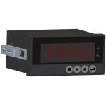
5 Red LED digital tubes for English&digit display With
Special Anti-vibration Digital Filtering Algorithm For Precise
Weighing
Terminal
| No. | Pin | Description |
| LOADCELL | Loadcell Port |
| Connection Mode | 6-Wire | 4-Wire |
| Internal Dip Switch S4 | S4→【6-WIRE】 | S4→【4-WIRE】
[Default Set] |
| 1 | SIG- | Weighing Signal [mV] Input -. | Weighing Signal [mV] Input -. |
| 2 | SIG+ | Weighing Signal [mV] Input +. | Weighing Signal [mV] Input +. |
| 3 | EXC- | Excitation Voltage -. | Excitation Voltage -. |
| 4 | SEN- | Feedback Voltage -. | |
| 5 | EXC+ | Excitation Voltage + [DC9V]. | Excitation Voltage + [DC9V]. |
| 6 | SEN+ | Feedback Voltage +. | |
| 7 | SHD | Shield Ground. | Shield Ground. |
| POWER | DC24V[±20%] Power Input Port |
| 1 | DC- | DC Input -. |
| 2 | DC+ | DC Input +. |
| The metal shell should be grounded directly. For separating the
controller from the interference of the driving devices, the DC24V
power supply of the controller should not be shared by the DO. |
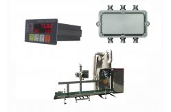
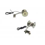
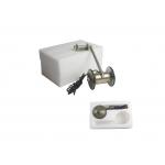
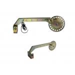
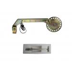
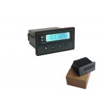
Pictures
Technical Specifications
Power Supply: DC24V±20%, Max. 5W.
Loadcell Excitation Voltage/Current: DC5V/120mA.
8 Loadcells[350Ω] connectable.
Transmitter Excitation Voltage/Current: DC12V/100mA.
Optional weighing input signal mV, V and mA.
【mV】Signal Input Range: 0~19.5mV.
【V】Signal Input Range: 0~2.5V, 0~5V, 0~10V.
【mA】Signal Input Range: 0~20mA.
2 Normally open/closed Relays [DO]: AC250V/DC24V, 1A.
1 Analog Signal Output [AO]: 0~20mA, 0.05%FS.
COM1: RS232.
COM2: RS485.
Connect Host IPC[Modbus] & Remote Display.
Outline Size [W×H×D]: 107 × 60 × 100 mm.
Panel Cut-out Size [W×H]: 94 × 47 mm.
Operating Temperature: -25℃~+45℃.
Protection Level of Front Panel: IP65.
Accuracy Grade: III.
Verification Accuracy: 0.03%.
Static Weighing / Force Measuring Accuracy: 0.2%~0.5%.
Data Display
| Name | Description | Range | Note |
| X | Channel X Real-time Force Value
or Peak Value. | -5000~+5000 | Refer to Parameters [202]~[207]. |
| Y | Channel Y Real-time Force Value
or Peak Value. | -5000~+5000 |
| Z | Channel Z Real-time Force Value
or Peak Value. | -5000~+5000 |
| [F] | Real-time Resultant Force or Resultant Force Peak Value [Force
Value Unit]. | 3-D Algorithm: F2 = X2 + Y2 + Z2
CUSUM Algorithm: F = X + Y + Z |
State Indication
| LED light | Description |
| [RUN] | OFF: Real-time Force Value tracking display state.
ON: Peak Value Detecting Result holding display state [Peak Value
Detecting Process Finished].
Blinking: Peak Value tracking display state [In Peak Value
Detecting Process]. |
| [AL1] | Real-time Resultant Force or Resultant Force Peak Value Upper Limit
Alarm.
Refer to Parameters [200]&[202]. |
| [AL2] | Real-time Resultant Force or Resultant Force Peak Value Lower Limit
Alarm.
Refer to Parameters [201]&[202]. |
Installation
DI/DO Connection for Typical Application