
Flexible Interface KLM800 Radar Level Sensor Module with Modbus Communication
|


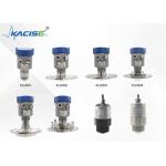
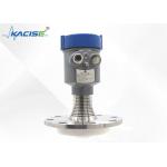
Product Description:Millimeter Wave Radar Components The millimeter wave radar component is mainly composed of the radio frequency unit, processing unit, and printed board antenna. Its detection capability surpasses light, rain, dust, fog or frost, and other obstacles. Therefore, it can successfully detect targets even under harsh environments. This sensor is small but powerful as it can work all day long. The millimeter wave radar has the advantage of high integration, small size, and flexible interface. Product Level Meter Radar The product level meter radar is designed based on millimeter wave radar, and it measures the height of radar antenna from the liquid level. It is widely used in the measurement of water resources such as rivers and reservoirs, as well as tank level and water level measurement. This device is highly efficient and reliable. Module Devices The modules can be derived from the following devices:
Features:● High integration ● Small volume ● Flexible interface ● It can detect targets through obstacles such as light, rain, dust, fog or frost ● Small sensors that work all day long
Technical Parameters:
Dimensions:
Applications:● River, reservoir and other water conservancy survey ● Tank level and water level measurement ● Water conservancy project ● Sewage treatment plan ● Petroleum chemical plant
Power supply and communicationThe module interface is shown in the following figure:
Equipment installation instructionsWhen installing the module, try to keep it fixed to avoid module jitter and keep the surrounding environment as open as possible. 1. The distance between the module and the water surface is higher than 30cm to ensure that the front face of the module (antenna surface) is parallel to the measuring liquid level; 2. The distance between the module and the edge of the tank, the edge of the pool, the edge of the river dam and the edge of the pool is greater than 1 meter; 3. choose the less volatile the location of the installation module (try not to install in the injection port and outlet undulation is big, the undulation, the greater the measurement precision, the worse). 4. Installation diagram Guarantee within the scope of the beam without distractions, such as Banks of the river bank. Points to note Module installation to maintain constant as far as possible, avoid module jitter, surrounding environment to open as much as possible. 1. The distance between the module and the water surface is higher than 30cm to ensure that the front face of the module (antenna surface) is parallel to the measuring liquid level 2. The distance between the module and the edge of the tank, the edge of the pool, the edge of the river dam and the edge of the pool is greater than 0.5 meters; 3. choose the less volatile the location of the installation module (try not to install in the injection port and outlet undulation is big, the undulation, the greater the accuracy of measurement, the worse)) A serial port communication protocol
For example, the sent data is FF 2A 4B 90 42 47, where FF is the frame header, the middle 4 bytes "2A 4B 90 42" is the distance information, and the size end sets its true information to 42 90 4B 2A (hexadimal floating point type), which is converted to decimal 72.1468 cm. 47 is a checksum, its calculation is as follows: First to convert floating point distance 72.1468 uint32_t integer (4 bytes) to 72, in low level in two bytes 0 (HEX 0), low of 72 (HEX 48) as the checksum as frame head low, high + + integer integer to take low 8 bits, (FF + 0 x00 + 0 x48) & 0 x47 x00ff = 0. Add: SScom test mode Can be tested using a serial port to help (hand SScom) : 1. Use the USB serial port module connected to the computer USB interface, open SSCOM serial debugging software, choice The correct port; 2.Send the AT + TLVS = 1 n, to convert the output string, according to send the command "AT + START n"; 3.The output string
Note: the default baud rate to 9600. If you open a string with no right side of SSCOM, click the extension to the right of "Save Parameters" to display it.
Notes: In the working state of the MCU, to configure, first send the reset command (interrupt the work), customize the input command, then send the reset command (make the configuration effective), and send the start command.
The MODBUS RTU communication protocol1.Setup instructions: function code 0 x10(1)Restore factory SettingsRequest command:
Data definition: 0 to restore the factory Settings, 1 to restart the program. Reply data:
Examples: Request: 7 f 10 10 00 00 02 00 00 9 e 33 01 Reply: 7 f 10 10 00 00 0 f 17 01 Where the data part 00 00 means to restore the factory Settings. (2)From the machine addressRequest command:
Data definition: value range 1--247. Reply data:
Examples: Request: 7F 10 20 01 00 01 02 00 01 6E 21 Reply: 7 f 10 20 01 00 01 51 D7 The data part 00 01 indicates that the slave address is set to 1.
(3)Range of measurementRequest command:
Data definition: The data value is Float data, the unit is meters, the data length value is 4 bytes, the data format is low 16 bits of data in the front, high 16 bits of data in the back. Reply data:
Examples: Request: 7 46 00 02 04 f 10 20 00 00 41 30 to 40 19 Re: 7F 10 20 46 00 02 A1 C3 00 00 41 30 into which the data portion of the floating-point data that is 11 meters.
(4)Measure the time intervalRequest command:
Data definition: Set the time interval of water level meter data collection, unit ms, and the minimum value is 100ms. Reply data:
Examples: Request: 7 2 e f 10 20 00 02 03 01 E8 A8 C0 Reply: 7F 10 20 2E 00 01 60 1E Among them, the data part 03 E8 is converted to decimal 1000, that is, the data acquisition interval is set to 1000ms.
(5)Communication baud rateRequest command:
Data definition: Communication baud rate: 4800,9600,19200.
Reply data:
Examples: Request: 7 f 10 20 00 02 01, 02, 25 80 B4 E2 Reply: 7F 10 20 02 00 01 A1 D7 The data part 28 80 means that the communication baud rate is set to 9600.
2.Query instruction: Function code 0x03(1)From the machine addressRequest command:
Reply data:
Data definition: value range 1--247. Examples: Request: 7 f 03 01 00 20 01 D4 14 Reply: 7 f 03 02 0 01 51 8 e The data part 00 01 means that the slave address is 1.
(2)Range abilityRequest command:
Reply data:
Data definition: The data value is Float data, the unit is meters, the data length value is 4 bytes, the data format is low 16 bits of data in the front, high 16 bits of data in the back. Examples: Request: 7 46 f 03 20 00 00 02 24 Reply: 7 f 03 04 00 00 41 30 54, 70 The data part 00 00 41 30 is converted to floating point data, which is 11 meters.
(3) Baud rate of communicationRequest command:
Reply data:
Examples: Request: 7 f 20 00 02 03 01 24 14 Re: 7F 03 02 25 80 8B 7E The data part 28 80 means the communication baud rate is 9600.
(4)Measure the time intervalRequest command:
Reply data:
Data definition: Set the time interval of water level meter data collection, unit ms, and the minimum value is 100ms. Examples: Request: 7F 03 20 2E 00 01 EF C3 Reply: 7 f 03 02 90 F0 03 E8 Among them, the data part 03 E8 was converted to decimal 1000, indicating that the data acquisition interval was 1000ms. (5)Query measurement resultsRequest command:
Reply data:
Data Definition: Data value is Float type data, the unit is meters. Data length value is 4 bytes, data format for the low 16 bits of data in the former, high 16 bit data behind. The meaning of the measurement result is associated with the type of measurement, and the default is the water level. Examples: Request: 7 4 0 f a 48 0 0 f 00 02 e Reply: 7 f 04 04 04 19 3 f 9 e 25 2 c The data part 04 19 3F 9E is converted to floating point data that is 1.2345 meters. 19049 e3f, in one place, with right high position. (6)Query versionRequest command:
Reply data:
Data definition: The data is in BCD encoding format, 0x20 0x23 0x05 0x12, which means data 20230512. (7)Broadcast address query devicesRequest command:
Reply data:
Data definition: 0x7F in the data is the 485 address of the device.
Support and Services:Our Accelerometer Sensor product technical support and services include:
Packing and Shipping:Product Packaging: The accelerometer sensor will be packaged in a sturdy cardboard box with cushioning material to prevent damage during transit. The box will also be labeled with the product name and any necessary handling instructions. Shipping: The product will be shipped via standard ground shipping unless expedited shipping is requested and paid for by the customer. Shipping costs will be calculated based on the destination and weight of the package. Customers will receive a tracking number once the package has been shipped. |
||||||||||||||||||||||||||||||||||||||||||||||||||||||||||||||||||||||||||||||||||||||||||||||||||||||||||||||||||||||||||||||||||||||||||||||||||||||||||||||||||||||||||||||||||||||||||||||||||||||||||||||||||||||||||||||||||||||||||||||||||||||||||||||||||||||||||||||||||||||||||||||||||||||||||||||||||||||||||||||
| Product Tags: Modbus Communication Radar Level Sensor Module Flexible Interface Radar Level Sensor Module |
|
Smaller Launch Angles And Multiple Measurement Modes KLD800 Series 80G Radar Level Gauge |

|
KLD800 Series 80GHz FMCW Radar Level Transmitter with Corrosion Resistant PTFE Antenna and 3° Launch Angle for Liquid and Solid Measurement |
|
KLD805 80GHz 76mm Lens Antenna Radar Liquid Level Transmitter For High Temperature And Pressure |

|
KLD803 PTFE Anti-Corrosion Radar Level Gauge with Small Blind Spot and 80GHz Frequency for Precise Level Measurement |

|
KLD801 80GHz FMCW Radar Level Transmitter with 32mm Lens Antenna and ±2mm Accuracy for Non-Contact Liquid Measurement |

|
KWL801B 80GHz Radar Water Level Meter with RS485 Output and Modbus Protocol for High Precision Measurement |