
High Precision Inertial Measurement Unit For Scaling Factor Repeatability Of 300
|
Product Description:Introduction The KSIMU03D is a top-of-the-line inertial measurement device
designed for precise navigation, control, and dynamic measurement
of weapons. Its compact size, high overload resistance, and
exceptional performance make it a go-to choice in the military
industry.Product Description The KSIMU03D series of products boasts full MEMS inertial devices.
The power supply, ADC, processor, and interface chip are procured
separately for optimized performance. The overall quality of the
product meets the common military standard, ensuring reliable and
consistent results.Key Features The KSIMU03D is made up of a three-axis gyroscope, a three-axis
accelerometer, a temperature sensor, a signal processing board, a
structure and necessary software. The device is designed to measure
the three-axis angular rate, three-axis acceleration, pitch and
roll angle of the carrier.Output and Communication The device is equipped with an RS-422 serial port that communicates
according to convention communication protocol. Additionally, the
device outputs error compensation data, which includes temperature
compensation, installation misalignment angle compensation,
nonlinear compensation, and so on. Gyroscope, accelerometer, and
pitch-roll angle data are all included in the output.Features:● Wide operating temperature range ● Wide bandwidth ● Small size ● Fast start ● High precision ● High reliability and high robustness ● Accurate measurement in harsh environment Technical Parameters:
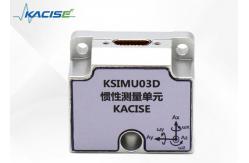
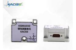
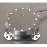
Dimensions:KSIMU03D inertia unit is shown in Figure 4 Figure 4 Appearance of the IMU The KSIMU03D is installed with three Φ4.4 through holes and three M4 screws (spring washer and flat washer). When the connector is installed, the plug should be locked with the socket and the cable should be fixed. It is recommended that the flatness and verticality of the installation surface relative to the base plane be no more than 0.02mm, no more than 0.04mm, and no more than 0.8μm of the surface roughness.
Spatial Coordinates: Right hand rule principle 1 The MEMS IMU contains three axial spatial coordinate systems, namely X, Y and Z. The X-axis points to the direction of the electrical connection interface, the Y-axis points to the left side of the IMU, and the Z-axis points to the top surface of the IMU, as shown in Figure 1. Figure 1 IMU Spatial coordinate
The installation of the IMU must match the axis of the coordinate system, otherwise the measured angular velocity data is not accurate. Following the "Right Hand Rule principle 1", you can quickly assign and determine the axis of the coordinate system. Extend your right hand and expand your thumb, index finger, and middle finger respectively. The thumb is pointing in the X-axis direction, the index finger is pointing in the Y-axis direction, and the middle finger is pointing in the z-axis direction, as shown in Figure 2. Figure 2 Principle 1 of the right-hand rule Right Hand Rule Principle 2 The three-degree-of-freedom gyroscope in the IMU measures angular velocities in three directions. Following the "right hand rule principle 2", the angular velocity direction of the axis rotation can be quickly determined. Stretch out the right hand and spread the thumb. The direction of the thumb is the axial direction, and the direction of the other four fingers is the direction of the axial rotation of the thumb, as shown in Figure 3. Figure 3 Principle 2 of the right-hand rule Definition of heading Angle, pitch Angle and rolling Angle Pitch angle definition: Taking the X- axis as the rotation axis, counterclockwise is positive, horizontal is zero, and the range is [-90º, 90º]. Roll angle definition: Taking the Y axis as the rotation axis, counterclockwise is positive, horizontal is zero, and the range is [-180º, 180º]. Course angle definition: Taking the Z axis as the rotation axis, counterclockwise is positive, north is zero, and the range is [-180º, 180º].
Electrical Characteristics:
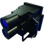
The electrical connector model of KSIMU03D is J30JE-15ZKN-J, and the corresponding connector model is J30J-15TJ. Contact specific distribution is shown in the table below.
Communication protocol The communication interface is RS422, with 8 data bits, 1 start bit, 1 stop bit, and no verification; the high byte is first and the low byte is last. The default baud rate at power-on is 460800, and the data update frequency is 500Hz.
Setup command 1 Setup preparation Stop output *0RM=D (Enter) Start output *0RM=U (Enter) 2 Set baud rate *BAUD=1 (Enter) Set the baud rate to 115200 *BAUD=2 (Enter) Set the baud rate to 230400 *BAUD=3 (Enter) Set the baud rate to 460800 *BAUD=4 (Enter) Set the baud rate to 921600 3 Set output frequency *FREQ=1 (Enter) Set the output frequency to 100Hz *FREQ=2 (Enter) Set the output frequency to 125Hz *FREQ=3 (Enter) Set the output frequency to 250Hz *FREQ=4 (Enter) Set the output frequency to 500Hz
Applications:Automotive Electronics Automotive electronics refers to the electronic systems used in vehicles to enhance their functionality and performance. These systems include electronic control units (ECUs), sensors, actuators, and communication devices that work together to regulate various aspects of the vehicle's operation. Aircraft Guidance and Control Aircraft guidance and control systems are critical to the safe operation of aircraft. These systems use advanced technologies such as GPS, autopilots, and flight management systems to help pilots navigate, maintain altitude and airspeed, and land safely. Attitude Reference System The attitude reference system is a key component of aircraft guidance and control. It provides accurate information about the aircraft's orientation in space, which is essential for maintaining stable flight and navigating accurately. Platform Stabilization Platform stabilization is used in a variety of applications, including cameras, telescopes, and radar systems. It involves the use of sensors, motors, and control systems to keep the platform steady and pointed in the desired direction, even in the presence of external disturbances. Robot, Antenna Stabilization Robot and antenna stabilization systems are used to keep these devices steady and pointed in the correct direction. They use advanced sensors and control algorithms to detect and compensate for external forces and disturbances, ensuring accurate and reliable performance. Support and Services:Our Electronic Gyroscope Sensor is designed to provide precise motion sensing in a variety of applications. Our product technical support and services are dedicated to ensuring that you can integrate and use our gyroscope sensor effectively in your projects. Technical Support: - Comprehensive online documentation: Access detailed product specifications, integration guides, and troubleshooting articles to assist you with any technical queries regarding our Electronic Gyroscope Sensor. Services: - Email support: Reach out to our dedicated support team for personalized assistance with any technical issues you may encounter. We are committed to providing you with the support you need to utilize our Electronic Gyroscope Sensor to its fullest potential. Packing and Shipping:Product Packaging: The Electronic Gyroscope Sensor comes securely packaged in an anti-static bag to prevent any electrostatic discharge during handling. The bag is then placed in a custom-fit foam insert that snugly holds the sensor in place, ensuring maximum protection against physical shocks and vibrations. This foam is encased in a sturdy cardboard box which is sealed and labeled with the product information and handling instructions. The packaging has been designed to be compact while offering the best possible protection for the sensitive electronics inside. Shipping: Once the Electronic Gyroscope Sensor is packaged, it is ready for shipping. The boxed product is placed in a secondary, larger cardboard box with additional cushioning material to fill any void space, minimizing movement during transit. Fragile stickers are applied to the outer box to alert couriers that the contents require careful handling. The package is then sealed with heavy-duty packing tape and dispatched using a reliable shipping service that provides a tracking number. Customers will receive their tracking information via email to monitor their package's journey until delivery. |
|||||||||||||||||||||||||||||||||||||||||||||||||||||||||||||||||||||||||||||||||||||||||||||||||||||||||||||||||||||||||||||||||||||||||||||||||||||||||||||||||||||||||||||||||||
| Product Tags: High precision inertial measurement unit 10mg inertial measurement unit | |||||||||||||||||||||||||||||||||||||||||||||||||||||||||||||||||||||||||||||||||||||||||||||||||||||||||||||||||||||||||||||||||||||||||||||||||||||||||||||||||||||||||||||||||||
|
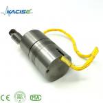
Dynamically Tuned Gyroscope For Well Logging for Temperature Sensor |

|
Well Logging Dynamically Tuned Gyroscope For High Temperature Environment |
|
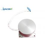
Single Axis Fiber Optic Electronic Gyroscope Sensor Shocking Resistance |
|
Gyroscope/Angular velocity sensor/Used to measure the angular velocity in the direction of the sensitive axis |

|
AI vision inertial navigation system for aircraft lifting assistance with weight ≤2.0kg |
|
State-of-the-Art Inertial Navigation System Aviation for Aviation Applications with Navigation accuracy (takeoff) 1.0m |