
Magnetometer for Handheld devices, Resolution 120ugauss, Non-linearity 0.1%,
|


Product Description
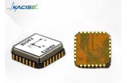
KSMIT3: A Self-Contained Attitude Heading and Reference System KSMIT3 is a state-of-the-art Attitude Heading and Reference System that comes as a fully functional self-contained module. Its design is based on a limited number of hardware components, which makes it easy to integrate into any system. This innovative system boasts a fully documented and industry-standard communication protocol, which allows for the customization of data messages in terms of frequency, output format, and data. The signal is processed entirely on the board, which only uses a small amount of resources on the host. This feature makes KSMIT3 ideal for use in simple MCU operating environments. KSMIT3 features high accuracy under dynamic conditions with flipping and pitching accuracy of 1 degree RMS, as well as a deflection accuracy of 2 degrees RMS. Its output is highly stable, making it perfect for use in the control and stabilization of any object or navigation, such as drones. Features
● Full performance AHRS on 12.1 x 12.1 mm modules ● Flip/pITch accuracy (dynamic) 1.0 degrees ● Heading accuracy 2.0 degrees ● Extremely low requirements for the main processor ● Unified interface for the entire product lifecycle ● Low power (45 mW at 3.0V) ● Compatible wITh PLCC28 PCB (12.1 x 12.1 x 2.6 mm)
Technical Parameters
Frames of reference
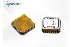
The KSMIT3 uses a right-handed coordinate system and the default sensor frame is defined as shown in Figure 13. For a more exact location of the sensor frame origin, refer to the Hardware Integration manual. Some of the commonly used data outputs wITh their output reference coordinate system are listed in Figure 1. Figure 1 Default Sensor Fixed Coordinate System for KSMIT3 Module
User communication protocol
The baud rate is 115200bps, 230400bps, and 460800bps. Data bIT 8, stop bIT 1, no check bIT. High bytes come first and low bytes come last. Data update frequency f=100Hz. The default baud rate is 230400bps.
Pin configuration Figure 2: Pin configuration of KSMIT3 module (top view)
Parameter settings
The product defaults to the "continuous output" state when powered on, and to set parameters, the "stop output" command must be sent first. Attention:After using the following command, the user must power on and restart to automatically swITch to the state of continuous transmission. 1 Stop output Stopping output is to swITch the default "continuous output" state on power to the "parameter setting" state. Sent to: * PA space GS01 space STOP carriage return Reply: * PA space GS01 space STOP space 0 carriage return Failed *PA space GS01 space STOP space 1 carriage return Successful 2 Set up work scenarios The product needs to swITch filter parameters according to different application scenarios. Work scenarios include car mounted, indoor (swing table)Shipboard, fixed wing, and rotor, wITh the default onboard scenario for power on. Scene swITching is to swITch the default "car scene" when powered on to the actual scene. Send: * PA space GS01 space SCENES space 1 carriage return Reply: * PA space GS01 space SCENES space 1 space 0 carriage return Failed *PA space GS01 space SCENES space 1 space 1 carriage return Successful Note: The underlined characters include 1- car mounted, 2- indoor, 3- ship mounted, 4- fixed wing, and 5- rotor optional. 3 Set Baud Rate The default baud rate for powering on is 230400bps, which can be swITched by sending commands. Send: * PA space GS01 space BAUD space 1 carriage return Reply: * PA space GS01 space BAUD space 1 space 0 carriage return Failed *PA space GS01 space BAUD space 1 space 1 carriage return Successful Note: The content of the underlined characters is 1-115200bps, 2-230400bps, and 3-460800bps, which are optional. 4 Restore factory settings Restoring factory settings involves setting the work scene, frame format, baud rate, magnetic declination, and magnetic field calibration to default values. Send: * PA space GS01 space RESET carriage return Reply: * PA space GS01 space RESET space 0 carriage return Failed *PA space GS01 space RESET space 1 carriage return Successful 5 Set magnetic declination angle The default magnetic declination is 0, wITh posITive magnetic north east and negative magnetic west. Send: * PA space GS01 space MDEC space+/- XX.XX carriage return Reply: * PA space GS01 space MDEC space 0 carriage return Failed *PA space GS01 space MDEC space 1 carriage return Successful Note: If the magnetic declination angle is -2.5 degrees, the underline string is -02.50; If the magnetic declination angle is+1.5 degrees, the underline string is+01.50. 6 Magnetic field calibration In the operation of magnetic sensors, IT is inevITable to be affected by the interference of surrounding electromagnetic fields, which can lead to varying degrees of deviation and deformation of the XYZ axis magnetic field strength measured by the magnetic sensor. Magnetic field calibration is to compensate for soft and hard magnetic interference through algorIThm learning of the surrounding magnetic field environment. Therefore, we strongly recommend that magnetic field calibration should be implemented after each installation and after changes in the magnetic field environment. When performing magnetic field calibration, the surrounding interfering substances should remain unchanged (i.e. rotate wITh the product) during the product rotation process and the relative posITion of the product. Calibration requires the operator to have no mobile phones, magnetic cards, keys, or metal or powered devices that can affect the electromagnetic field on their body. Attention: Only wIThin the limITed interference range can the magnetic field calibration operation have a compensation effect. The range of the magnetic sensor is approximately between plus and minus 1 Gauss, which is approximately twice the geomagnetic field in the northern hemisphere. If the magnetic field interference value exceeds plus or minus 0.5 Gauss, the magnetometer may reach saturation state, which hinders the compensation effect. When calibration fails, IT indicates that the problem has occurred. 2D calibration Note: When the product cannot rotate in 3D, 2D calibration can be used. IT is recommended that the actual tilt angle of the product be less than 5 degrees. 2D calibration can be completed through the interface or serial port by issuing commands. 1. Start calibration: Before user calibration, send Send: * PA space GS01 space MCAL space START carriage return Reply: * PA space GS01 space MCAL space START space 0 carriage return Failed *PA space GS01 space MCAL space START space 1 carriage return Successful 2 Stop calibration: Start horizontal rotation for more than 2 turns, and send after completion Send: * PA space GS01 space MCAL space END carriage return Reply: * PA space GS01 space MCAL space 0 carriage return Failed *PA space GS01 space MCAL space 1 space X: x.xx space Y: y.yy carriage return Successful Note: Returning calibration results of 0.90-1 indicates good calibration results, while>1.1 or<0.9 indicates poor calibration results. 3. Save calibration results: After user calibration, decide whether to save based on the calibration results. Send: * PA space GS01 space MCAL space SAVE carriage return Reply: * PA space GS01 space MCAL space SAVE space 0 carriage return Failed *PA space GS01 space MCAL space SAVE space 1 carriage return Successful 4. Clear calibration results: After calibration, the user decides whether to clear based on the calibration results. Send: * PA space GS01 space MCAL space CLEAR carriage return Reply: * PA space GS01 space MCAL space CLEAR space 0 carriage return Failed *PA space GS01 space MCAL space CLEAR space 1 carriage return Successful ApplicationsMiniature aerial vehicles • Delivery drones • Video drones • Agricultural UAVs Machinery • Satcom on the Move (SotM) • Construction machinery • Ship monIToring Robotics • Autonomous agriculture • Warehouse automation • Robotic arms Other applications • Handheld devices • Pedestrian navigation • VR/AR and HMDs •Navigation aiding
Support and Services:Welcome to our Technical Support and Services for the Gyroscope Sensor. Our dedicated team is here to assist you with any technical issues or inquiries you may have regarding the use, installation, or maintenance of your gyroscope sensor. We are committed to providing you with the best possible support to ensure your product functions optimally.
Our support includes detailed product documentation, frequently asked questions (FAQs), and troubleshooting guides designed to help you resolve common issues quickly. For more complex or specific concerns, our technical support team is ready to provide personalized assistance.
If you require further assistance, please refer to the 'Contact Us' section of our website (contact information excluded as per request) where you can find additional resources and support channels to get in touch with our professional technical support team.
Thank you for choosing our Electronic Gyroscope Sensor. We look forward to serving you and ensuring the success of your projects Packing and Shipping:The Electronic Gyroscope Sensor is meticulously packaged in an anti-static bag to ensure protection against electrostatic discharge (ESD). The sensor is then securely encased in a custom-fit, high-density foam mold, which provides superior shock absorption during transit. This foam is placed within a durable, branded cardboard box that shields the sensor from environmental factors and potential damage while in transit.
The exterior of the box features clear labeling with the product name, handling instructions, and a barcode for easy tracking. All our packages are sealed with tamper-evident tape, offering an additional layer of security.
For shipping, the Electronic Gyroscope Sensor is dispatched via a trusted courier service to ensure timely and safe delivery. We include insurance for the full value of the product, offering peace of mind and protection for your investment. Tracking information is provided as soon as the package is dispatched, allowing for real-time monitoring of the shipment until it arrives at its destination.
|
||||||||||||||||||||||||||||||||||||||||||||||||||||||||||||||||||||||||||||||||||||||||||||||||||||||||||||||||||||||||||||||||||||||||||||||||||||||||||||||||||||||||||||||||||||||||||||||||||||||||||||||||||||||||||||||||||||||||||||||||||||||||||||||||||||||||
| Product Tags: Non-linearity 0.1% Magnetometer Magnetometer for Handheld devices | ||||||||||||||||||||||||||||||||||||||||||||||||||||||||||||||||||||||||||||||||||||||||||||||||||||||||||||||||||||||||||||||||||||||||||||||||||||||||||||||||||||||||||||||||||||||||||||||||||||||||||||||||||||||||||||||||||||||||||||||||||||||||||||||||||||||||
|
Dynamically Tuned Gyroscope For Well Logging for Temperature Sensor |

|
Well Logging Dynamically Tuned Gyroscope For High Temperature Environment |
|
Single Axis Fiber Optic Electronic Gyroscope Sensor Shocking Resistance |
|
Gyroscope/Angular velocity sensor/Used to measure the angular velocity in the direction of the sensitive axis |

|
AI vision inertial navigation system for aircraft lifting assistance with weight ≤2.0kg |
|
State-of-the-Art Inertial Navigation System Aviation for Aviation Applications with Navigation accuracy (takeoff) 1.0m |