
Inertial Measurement Device Operating Temperature -40~75℃ One SPI 15MHz Solid And Reliable
|


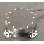
Product Description:Inertial measurement Unit KSIMU16495 is a domestic inertial measurement equipment with high performance, small size and high overload resistance. Gyroscope zero bias stability 0.5°/h (Allan), accelerometer zero bias stability 10µg (Allan). It can be used for precise navigation, control and dynamic measurement of weapons. This series of products adopts high-precision MEMS inertial devices, with high reliability and high robustness, and can accurately measure the angular velocity and acceleration information of the moving carrier in harsh environments. The inertial measurement unit KSIMU16495 with built-in three-axis gyro and three-axis accelerometer is used to measure the carrier's three-axis angular rate and three-axis acceleration. Through the serial port according to the convention communication protocol output error compensation (including temperature compensation, installation misalignment Angle compensation, nonlinear compensation, etc.) gyroscope, accelerometer data, and built-in three-axis magnetic sensor, pressure sensor.
Features:● High precision MEMS inertial navigation ● Support dynamic fast alignment ● High bandwidth, high data update rate ● 1 channel SPI ● Small size, light weight ● Solid and reliable ● Fully compatible with a foreign 10 degrees of freedom inertial measurement system
Technical Parameters:
Dimensions:
Coordinate System Definition:
The coordinate system of the gyroscope and accelerometer is defined as shown in the figure below, with the arrow direction being positive.
Read and Write Data:The KSIMU16495 is an automatic sensor system that automatically activates when an active power supply is present. After completing the initialization process, it begins sampling, processing, and loading calibrated sensor data into the output register, which can be accessed through the SPI port. The SPI port is usually connected to the compatible port of the embedded processor, the connection diagram is shown in the following figure. Four SPI signals support synchronous serial data transmission. In the factory default configuration, the DIO2 pin provides a data ready signal; When new data is available in the output data register, the pin becomes high level.
Common Host Processor SPI Settings:
SPI Communication:If the previous command is a read request, the SPI port supports full-duplex communication, and the external processor can write to DIN while reading the DOUT, as shown below. SPI read-write timing Read sensor data KSIMU16495 automatically starts and activates page 0 for data register access. After accessing any other pages, 0x00 should be written to the PAGE_ID register (DIN = 0x8000) to activate page 0, ready for subsequent data access. A single register read operation requires two 16-bit SPI cycles. In the first cycle, the bit allocation function in Figure 1 is used to request a read of the contents of a register; In the second cycle, the contents of the register are output via DOUT. The first digit of the DIN command is 0, followed by the high or low address of the register. The last 8 bits are irrelevant bits, but SPI needs the full 16 SCLKS to receive the request. The following figure shows two successive register reads, first DIN = 0x1A00, requesting the contents of the Z_GYRO_OUT register, and then DIN = 0x1800, requesting the contents of the Z_GYRO_LOW register.
Example of SPI read operation User register memory mapping (N/A means not applicable)
transformation formula Current temperature = 25+ TEMP OUT*0.00565
Y-axis Z-axis gyro is calculated in a similar way to X-axis gyro.
Y-axis Z-axis accelerometer is calculated in a similar way to X-axis accelerometer.
Y-axis Z-axis magnetometer is calculated in a similar way to the X-axis magnetometer
Note: Gyroscope, accelerometer, magnetometer is divided into high 16bit and low 16bit, respectively calculated to add the final result
Electrical Interface:
|
|||||||||||||||||||||||||||||||||||||||||||||||||||||||||||||||||||||||||||||||||||||||||||||||||||||||||||||||||||||||||||||||||||||||||||||||||||||||||||||||||||||||||||||||||||||||||||||||||||||||||||||||||||||||||||||||||||||||||||||||||||||||||||||||||||||||||||||||||||||||||||||||||||||||||||||||||||||||||||||||||||||||||||||||||||||||||||||||||||||||||||||||||||||||||||||||||||||||||||||||||||||||||||||||||||||||||||||||||||||||||||||||||||||||||||||||
| Product Tags: Solid Inertial measurement device 15MHz Inertial measurement device reliable Inertial measurement device | |||||||||||||||||||||||||||||||||||||||||||||||||||||||||||||||||||||||||||||||||||||||||||||||||||||||||||||||||||||||||||||||||||||||||||||||||||||||||||||||||||||||||||||||||||||||||||||||||||||||||||||||||||||||||||||||||||||||||||||||||||||||||||||||||||||||||||||||||||||||||||||||||||||||||||||||||||||||||||||||||||||||||||||||||||||||||||||||||||||||||||||||||||||||||||||||||||||||||||||||||||||||||||||||||||||||||||||||||||||||||||||||||||||||||||||||

|
Dynamically Tuned Gyroscope For Well Logging for Temperature Sensor |

|
Well Logging Dynamically Tuned Gyroscope For High Temperature Environment |
|
Single Axis Fiber Optic Electronic Gyroscope Sensor Shocking Resistance |
|
Gyroscope/Angular velocity sensor/Used to measure the angular velocity in the direction of the sensitive axis |

|
AI vision inertial navigation system for aircraft lifting assistance with weight ≤2.0kg |
|
State-of-the-Art Inertial Navigation System Aviation for Aviation Applications with Navigation accuracy (takeoff) 1.0m |