
Inertial Measurement Unit Integrating Three Accelerometers And Gyroscope And Inclinometer
|
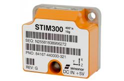
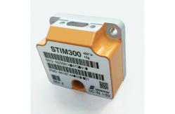
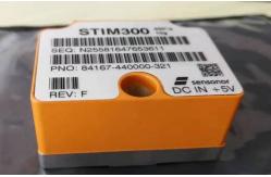
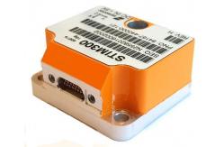
Inertial Measurement Unit STIM3001 FEATURES: ● Miniature package ● Low noise ● Low bias instability ● Excellent performance in vibration and shock environments ● 9 axes offered in same package ● Electronically calibrated axis alignment ● Gyros based on Safran ButterflyGyroTM ● Single-crystal silicon technology ● No intrinsic wear-out effects ● High stability accelerometers and inclinometers ● Insensitive to magnetic fields ● Full EMI compliance ● Digital interface, RS422 ● Fully configurable ● Continuous self-diagnostics ● RoHS compatible
2 GENERAL DESCRIPTION STIM300 is an IMU consisting of 3 high accuracy MEMS-based gyros, 3 high stability accelerometers and 3 high stability inclinometers in a miniature package. Each axis is factory-calibrated for bias, scale factor and compensated for temperature effects to provide high-accuracy measurements in the temperature range -40°C to +85°C. The unit runs off a single +5V supply. STIM300 communicates via a standard high-level RS422 interface. The use of a 32-bit RISC ARM microcontroller provides flexibility in the configuration, like choice of output unit, sample rate, low pass filter -3dB frequency and RS422 bit-rate and protocol parameters. All configurable parameters can be defined when ordering or set by customer. When STIM300 is powered up, it will perform an internal system check and synchronize the sensor channels. As an acknowledgement of the complete power-up sequence, it will provide special datagrams containing part number, serial number, configuration and bias trim data. STIM300 will then automatically proceed to provide measurement data. The measurement data is transmitted as packages of data on a fixed format (datagram) at intervals given by the sample rate together with a synchronization signal (TOV). The datagram is in binary coded format in order to have an efficient transfer of data. In addition to the measurement data itself, the datagram contains an identifier, status bytes and a 32 bit CRC (Cyclic Redundancy Check) to provide high degree of fault detection in the transmissions. The status bytes will flag any detected errors in the system. STIM300 can also be configured to transmit data only when triggered by a separate digital input signal (ExtTrig). For more advanced users, the gyro may be put in Service Mode. In this mode all the configuration parameters can be intermediately or permanently changed by overwriting the current settings in the flash memory. In Service Mode the commands and responses are in a human readable format (ASCII); to enable the use of terminal-type software during typical product integration. Service Mode also provides the ability to perform single measurements, perform diagnostics and obtain a higher detail level of detected errors reported in the status bytes. Finally, STIM300 may be put in Utility Mode. This mode is similar to Service Mode, but made for machine-machine communication.
3 BLOCK DIAGRAM: 4 ABSOLUTE MAXIMUM RATINGS Stresses beyond those listed in Table 4-1may cause permanent damage to the device. Exposure to any Absolute Maximum Rating condition for extended periods may affect device reliability and lifetime. Table 4-1: Absolute maximum ratings
5 SPECIFICATIONS Table: Operating conditions
Note 1: Other ranges available, ref.Table 5-4(5g),Table 5-6(30g) andTable 5-7(80g) Note 2: At supply voltages above 5.85V (nominal value) an internal voltage protection circuit will cut power and the unit will go into reset until the voltage is back within operating conditions. Note 3: At supply voltages below 4.05V (nominal value) the unit will go into reset until the voltage is back within operating conditions. Due to power consumption being much lower in reset compared to normal operation, the series resistance between power source and STIM300 could give rise to an oscillating behavior of the input voltage to the unit.
Table: Functional specifications, general
Note 1: Time from Power-On to start of datagram transmissions (starting with part-number datagram) Note 2: Time from Reset release to start of datagram transmissions (starting with part-number datagram) Note 3: Time from Power-On or Reset to the reset of the Start-Up bit (Bit 6 in the STATUS byte ref.Table 5-23). During this period the output data should be regarded as non-valid. Note 4: If a user-defined bit-rate larger than 1.5Mbit/s is used, the deviation may exceed the specification due to the resolution of the bit-rate generator, ref. section9.13.1 Note 5: Other values can be configured, ref.Table 5-11 Note 6: If time between triggers is longer than 127ms, the sample counter will over-run Note 7: Time between triggers should be carefully evaluated as long time between triggers in combination with high bandwidths could lead to issues related to folding. Similar for accelerometer and inclinometer outputs Note 8: If time between triggers is longer than 8ms, an overload may occur in the incremental angle. An overload will be flagged in the status byte, ref.Table 5-23. Similar for accelerometer and inclinometer outputs Note 9: If time between triggers is longer, the accuracy of average rate may also be reduced. Similar for accelerometer and inclinometer outputs Note 10: If time between triggers is longer, the integrated angle may have wrapped several times and hence the change in angle from last sample will not be possible to calculate. Similar for accelerometer and inclinometer outputs Note 11: For definition, ref.Figure 7-3 Note 12: Digital output level can be configured to 5V or 3.3V in SERVICEMODE (ref. section9.7) or when ordering (ref. section12) Note 13: For definition, ref.Figure 7-4andFigure 7-5
|
|
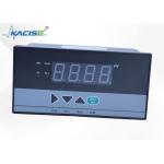
KDI Series Measurement Display Controller With Parameter Password Lock And Power - Off Retention |
|
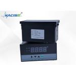
KDI Series Display Controller with AC/DC Switching Power Supply Option |
|
KDI Series Display Controller Compatible with Standard Indexing Temperature Sensors |
|
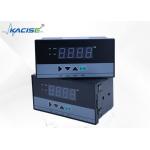
KDI Series Clear And Intuitive 40 - Line Light Column Display Controller |

|
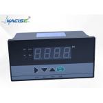
Digital Auto-tuning Function KDI Series Digital Display Controller With Measuring Range -1999-9999 Accuracy 0.2% FS ±1 |
|
KDI Series Display Controller Supporting Multi - Machine Communication |