
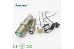
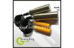
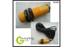
small waterproof Ultrasonic transducer with protecting grade IP67
|
|
Small waterproof Ultrasonic transducer
Features of Ultrasonic transducer
This sensor provides very short to long-range detection and ranging, in a compact, robust PVC or stainless steel housing, designed to meet IP67 water intrusion. The power 9.0V-28V operation detects objects from 0.1meters to 10meters and provides sonar range information from 0.25meters out to 10meters out with 0.001meters or 0.01meters resolution. The interface output formats included are pulse width output, analog voltage output 0/4-20mA current output, NPN/PNP output and RS485,RS232 output modbus-RTU and modbus-ASCII supported.
External synchronization
The sensor can be synchronized by the external application of a square wave voltage. A synchronization pulse at the synchronization input starts a measuring cycle. The pulse must have a duration greater than 100 μs. The measuring cycle starts with the falling edge of a synchronization pulse. A low level > 1 s or an open synchronization input will result in the normal operation of the sensor. A high level at the synchronization input disables the sensor. Two operating modes are available: 1. Multiple sensors can be controlled by the same synchronization signal. The sensors are synchronized. 2. The synchronization pulses are sent cyclically to individual sensors. The sensors operate in multiplex mode.
Internal synchronization
The synchronization connections of up to 5 sensors capable of internal synchronization are connected to one another. When power is applied, these sensors will operate in multiplex mode. The response delay increases according to the number of sensors to be synchronized. Synchronization cannot be performed during TEACH-IN and vice versa. The sensors must be operated in an unsynchronized manner to teach the evaluation limits. Note: If the option for synchronization is not used, the synchronization input has to be connected to ground (0V) or the sensor has to be operated via a V1 cable connector (4-pin).
Adjusting the evaluation limits
The ultrasonic sensor features an analogue output with two teachable evaluation limits. These are set by applying the supply voltage - UB or + UBto the TEACH-IN input. The supply voltage must be applied to the TEACH-IN input for at least 1 s. LEDs indicate whether the sensor has recognized the target during the TEACH-IN procedure. The lower evaluation limit A1 is taught with - UB, A2 with + UB. Two different output functions can be set: 1. Analogue value increases with rising distance to object (rising ramp) 2. Analogue value falls with rising distance to object (falling ramp) Evaluation limits may only be specified within the first 5 minutes after Power on. To modify the evaluation limits later, the user may specify the desired values only after a new Power On.
TEACH-IN rising ramp (A2 > A1)
- Position object at lower evaluation limit - TEACH-IN lower limit A1 with - UB - Position object at upper evaluation limit - TEACH-IN upper limit A2 with + UB TEACH-IN falling ramp (A1 > A2): - Position object at lower evaluation limit - TEACH-IN lower limit A2 with + UB - Position object at upper evaluation limit - TEACH-IN upper limit A1 with - UB
Default setting
A1: unusable area A2: nominal sensing range Mode of operation: rising ramp
Adjusting the sound cone characteristics of Small waterproof Ultrasonic transducer
The ultrasonic sensor enables two different shapes of the sound cone, a wide angle sound cone and a small angle sound cone. 1. Small angle sound cone - switch off the power supply - connect the Teach-input wire to -UB - switch on the power supply - the red LED flashes once with a pause before the next. - yellow LED: permanently on: indicates the presence of an object or disturbing object within the sensing range - disconnect the Teach-input wire from -UB and the changing is saved 2. Wide angle sound cone - switch off the power supply - connect the Teach-input wire with + UB - switch on the power supply - the red LED double-flashes with a long pause before the next. - yellow LED: permanently on: indicates an object or disturbing object within the sensing range - disconnect the Teach-input wire from + UB and the changing is saved Installation conditions If the sensor is installed at the environment temperature fall below 0°C,It should do well on the protective measures. In case of direct mounting of the sensor in a through hole using the steel nuts, it has to be fixed at the middle of the housing thread.
Our Services
After-sales service
We promise to deliver the following after-sales service: 1. Warranty: The warranty period is 12 months starting from the shipping date; 2. Customers will enjoy free repair services for failures found within the warranty due to manufacturing quality; 3. We provide paid repair services for meter damages not arising from manufacturing quality issues or meter damages not within the scope of warranty.
Company Information
|
|
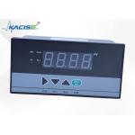
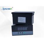
KDI Series Measurement Display Controller With Parameter Password Lock And Power - Off Retention |
|
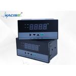
KDI Series Display Controller with AC/DC Switching Power Supply Option |
|
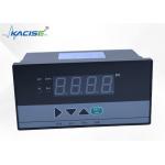
KDI Series Display Controller Compatible with Standard Indexing Temperature Sensors |
|
KDI Series Clear And Intuitive 40 - Line Light Column Display Controller |

|
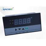
Digital Auto-tuning Function KDI Series Digital Display Controller With Measuring Range -1999-9999 Accuracy 0.2% FS ±1 |
|
KDI Series Display Controller Supporting Multi - Machine Communication |