
5000ppm-500000ppm Gas Detector Sensor Co2 Sensor Module Fast Response
|
|
KCS530 Infrared CO2 Module
1. OverviewKCS530 is a gas detection module based on the principle of NDIR infrared absorption, which is suitable for detecting the concentration of carbon dioxide in a gaseous environment at room temperature. KCS530 adopts a patented optical cavity, imported light source and dual-channel detector to realize the reference compensation of dual optical paths in space. KCS530 has good selectivity, no oxygen dependence and long life. KCS530 has UART, 485 output and 4-20mA current output (or analog voltage output) for easy application selection; The KCS530 provides zero point calibration, sensitivity calibration and clean air calibration commands, and provides a manually calibrated MCDL pin for customers to perform relative zero calibration of the sensor module using outdoor free-flowing clean air. KCS530 adopts convection diffusion ventilation mode, which has a fast diffusion speed. KCS530 is designed for CO2 concentration measurement in high humidity environments such as mushroom houses, incubation rooms, and agricultural greenhouses. It can also be widely used in HVAC fresh air control, indoor air quality monitoring, agricultural and animal husbandry production process monitoring, can be installed in intelligent buildings, ventilation systems, robots, automobiles and other applications, can also be applied to other narrow space air quality monitoring.
2. Technical Parameters
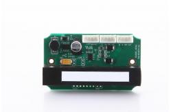
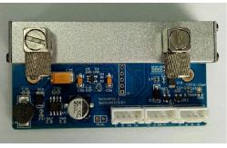
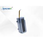
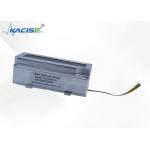
3. Structural Dimension DrawingUnit: mm
Diffusion
Pump-suction type
4.Signal OutputSignal output: analog current/voltage output, UART output, 485 output, users can need to customize. 4.1.Analog current/voltage outputAnalog current output range (4mA~20mA), 4mA corresponds to 0ppm, 20mA corresponds to gas concentration at full scale. Customers can also customize. Analog voltage output range (0.4V~2.0V), 0.4V corresponds to 0ppm, and 2.0V corresponds to the gas concentration at full scale. Customers can also customize. 4.2.UART communication protocolBaud rate: 9600bps, 8 data bits, 1 stop bit, no check bit; The data is ASCII output, the number of data bytes per frame is not fixed, starting with 32 and ending with rn It is divided into proactive upload and Q&A2way. 4.2.1 The sensor actively uploads the concentration value, and the data is output in the form of ASCII code, the format is as follows:
where 32 is the ASCII code for a space, and the output ends with a newline character For example: Output 12345 ppm format as follows:
4.2.2 Q&A (Choose one method for automatic upload and Q&A output, the default is active upload) Send decimal: 235237363521 return
where 32 is the ASCII code for a space, and the output ends with a newline character 4.3.MODBUS communication protocolTHREE PROTOCOLS ARE AVAILABLE: MODBUS RTU, MODBUS ASCII OR MODBUS CUSTOMIZATION. 4.3.1 MODBUS custom protocolHost send protocol format A protocol consists of fixed-format packets. The size of the packet varies depending on the content of the packet.
The address of the first byte communication unit of the packet: This refers to the address of the lower computer unit when the host communicates with the lower computer. The second byte of the packet is STX character, which is fixed. The third byte of the packet indicates whether the packet is a read command or a write command. 0x52 is to read the command 0x53 write the command. The fourth byte of a packet is the bit length describing the data contained in the entire message, which is equal to the packet size minus 6. Data is transferred sequentially from low byte to high byte. Text is routed from left to right. Once all data has been transferred, the end of the data will be indicated by 1 byte 0x21. The last byte of the protocol is the checksum to verify the correctness of the transmitted data. The device returns the protocol format A protocol consists of fixed-format packets. The size of the packet varies depending on the content of the packet.
Address of the communication unit: This refers to the address of the lower computer unit when the host communicates with the lower computer. The second byte of the packet is STX character, which is fixed. The third byte of the packet indicates whether the packet is a read command or a write command. 0x52 is to read the command 0x53 write the command. The fourth byte of a packet is the bit length describing the data contained in the entire message, which is equal to the packet size minus 6. Data is transferred sequentially from low byte to high byte. Text is routed from left to right. Once all data has been transferred, the end of the data will be indicated by 1 byte 0x21. The last byte of the protocol is the checksum to verify the correctness of the transmitted data. Command type (1) Read the sensor concentration value: such as reading the current No. 32 (20H) sensor data The host sends the command to the sensor: 20235201372146 20 23 52 01 37 21 ?? (decimal 16). 20: Sensor number 23: STX fixed 52: Read 01: Data length, indicating that there is 1 bit of data after it 37: Read sensor data 21: End ??: CheckSum check character CheckSum= 20⊕23⊕52⊕01⊕37⊕21=46H, so?? =46H The device will return the following data: 062023520537000003E821?? 06 20 23 52 05 37 00 00 03 E8 21 ?? (decimal 16). 06: ACK is correct 20: Returns the sensor address 23: STX (0x23) 52: Service Type The default return operation type is (0x52) read operation 05: Data Length The length of the data is 5 bytes 37: Command class 00 00 03 E8: The current CO2 concentration value, in PPM, is the concentration value expressed in 4 bytes, with the high concentration byte on the left and the low concentration byte on the right, depending on the concentration of the sensor 21: Ending character ?? : CheckSum check character CheckSum= 20⊕23⊕52⊕05⊕37⊕00⊕00⊕ 03⊕E8⊕21=?? XOR, excluding the first byte 06 (2) Set the sensor address: For example, read the current sensor address number 32 (20H) to number 34 (22H). The host sends the command to the sensor: 2023530231222160 20 23 53 02 31 22 21 ?? (decimal 16). 20: Current sensor number 23: STX fixed 53: Write 02: Data length, indicating that there are two digits of data after it 31: Write address command 22: The current sensor address is changed to number 34 21: End ??: CheckSum check character CheckSum= 20⊕23⊕53⊕02⊕31⊕22⊕21=60H, so ?? =60H The device returns the following data: 062023530231222160 06 20 23 53 02 3122 21 ?? 06: ACK is correct 20: Original sensor address 23: STX (0x23) 53: Service Type The default return operation type is (0x520) read operation 02: Data Length Data length 2 bytes 31: Class command class 22: The current sensor address after changing the address 21: Ending character ??: CheckSum check character CheckSum= 20⊕23⊕53⊕02⊕31⊕22⊕21=60H, so ?? =60H (3) About setting the initial address of the sensor: Short MCDL, zero calibration within 8 seconds, more than 10 seconds for the initial address of the sensor The default is number 32. The factory address of each sensor is set to 32 (20H), and when the user modifies the sensor address, the corresponding forehead button must be continuously held down for more than 10 seconds to restore the address factory setting. 4.3.2 MODBUS RTU ProtocolHost send protocol format A protocol consists of fixed-format packets. The size of the packet varies depending on the content of the packet.
Address of the communication unit: This refers to the address of the lower computer unit when the host communicates with the lower computer. The second byte of the packet indicates whether the packet is a read command or a write command. 03 indicates that the message is a read command, and 06 indicates that the message is a write command. CRC is used for verification to verify the correctness of transmitted data. Data is transferred sequentially from low byte to high byte. Text is routed from left to right. After all data is transmitted, the CRC check low and high bits will end. The device returns the protocol format A protocol consists of fixed-format packets. The size of the packet varies depending on the content of the packet. Command type (1) Read the sensor concentration value: such as reading the current sensor data No. 32 (20H). The host sends a command to the sensor: 20 03 00 00 00 02 C2 BA 20: Current sensor address 03: Read the sensor concentration 00 00 00 02: Data area content 00 00 is address 00 02 is quantity C2: CRC high BA: CRC low The basic principle of cyclic redundancy check code (CRC) is: after the K bit information code, then splicing the R bit check code, the entire coding length is N bits, therefore, this code is also called (N, K code. For a given ( N,K ) code , it can be shown that there exists a polynomial G(x) with a highest power of N-K = R. A checksum of K-bit information can be generated from G(x), and G(x) is called the generative polynomial of this CRC code. The specific generation process of the check code is: assuming that the information to be sent is represented by the polynomial C(X), shift C(x) to the left by R bits (which can be expressed as C(x)*2R), and so on To the right of C(x), the R bit will be free, which is the position of the check digit. The remainder obtained by dividing C(x)*2R to generate the polynomial G(x) is the check digit. The device returns the following data: If the total range is within 65536 ppm: 20 03 04 00 20 0B E8 CD 85 (decimal). If the total range is greater than 65536 ppm: 20 03 06 00 20 00 00 0B E8 33 9D (decimal). 20: Current sensor address 03: Read the sensor concentration 04/06: Data area length (The length of the returned data area is related to the total range ordered by the customer, if the maximum range ordered by the customer is within 65536 ppm, then the returned data area length is 04 (100ppm return number: 20 03 04 00 20 00 64 CB 10 ), if the maximum range is greater than 65536 ppm then the returned data area length is 06 (100 ppm return number: 20 03 06 00 20 00 00 00 64 35 08) The red part is the data bit, and the blue part is the data area length 00 20 : Displays the current sensor address 0x20 0B E8: Displays the sensor gas concentration in PPM, the specific value depends on the address and concentration of the sensor The above data are all decimal numbers, and it is necessary to convert them to base 10 numbers before calculating the concentration value For example: If the total range is within 65536 ppm: 0B is decimal 11; The decimal of E8 is 232, then the concentration value is: 11*256+232=3048 (ppm value of decimal). If the total range is greater than 65536 ppm: 00 is 0 for decimal; 0B is 11 for decimal; The decimal of E8 is 232, then the concentration value is: 0*65536+11*256+232=3048 (ppm value in decimal). CD: CRC high 85: CRC low CRC check values refer to the same as above (2) Set the sensor address: For example, change the sensor address of 32 (20H) to 01 The host sends a command to the sensor: 20 06 00 00 00 01 4E BB (decimal). 20: Current sensor address 06: Function code (set sensor address). 00 00 00 01: Data area (modified sensor new address 00 01, i.e. 01). 4E: CRC high BB: CRC low The CRC check value is the same as above The device returns the following data: 20 06 00 00 00 01 4E BB (decimal). Same as input After changing the address, the new reading command only needs to change the first address to the current address after the modification and perform CRC verification to obtain a new check bit: 01 03 00 00 00 02 C4 0B (decimal). The device returns the following data: If the total range is within 65536 ppm: 01 03 04 00 01 0B E8 AC 8D (decimal). If the total range is greater than 65536 ppm: 01 03 06 00 01 00 00 0B E8 1B CB (decimal). The new set sensor address command is: 01 06 00 00 00 XX xx xx XX: is the address that needs to be modified again xx xx: New check digit *This command is the serial port debugging assistant command modbus poll under the data display window, double-click the address display table to set a new address by modifying value (3) About setting the initial address of the sensor Short MCDL, zero calibration within 8 seconds, more than 10 seconds for the initial address of the sensor The default is number 32. The factory address of each sensor is set to 32 (20H), and when the user modifies the sensor address, the address must be restored by holding the corresponding forehead button continuously for more than 10 seconds. 4.3.3 MODBUS ASCII LICENSEHost send protocol format A protocol consists of fixed-format packets. The size of the packet varies depending on the content of the packet.
Address of the communication unit: This refers to the address of the lower computer unit when the host communicates with the lower computer. The first byte of the packet is 0x3a the last two bytes are 0x0d 0x0a and fixed. The fourth and fifth byte of a packet indicates whether the packet is a read command or a write command. 03 indicates that the message is a read command, and 06 indicates that the message is a write command. LRC is used for verification to verify the correctness of the transmitted data. Data is transferred sequentially from low byte to high byte. Text is routed from left to right. When all data is transferred, the data is 0x0d by 2 cut-off bytes and 0x0a indicates the end of the data. The device returns the protocol format A protocol consists of fixed-format packets. The size of the packet varies depending on the content of the packet. The return format is the same as the sending format. Command type (1) Read the sensor concentration value: such as reading the current 20H sensor data The address under the 03 function code under the Modbus poll should be set to 3 for 0x0003, and the quantity should be set to 1 . The host sends the command to the sensor: 3A 32 30 30 33 30 30 30 33 30 30 30 31 44 39 0D 0A (decimal) is: 200300030001D9 3a: Fixed start bit 32 30 is 20: sensor number 30 33 is 03: read sensor concentration 30 30 30 33 30 30 30 31: Data area content 30 30 30 33 address indicates that the register to be read has a starting address of 0x0003, and 30 30 30 31 is quantity means the number of registers to be read is 1 44: LRC high 39: LRC low 0D: Fixed end bit 0A: Fixed end bit LRC=20+03+00+03+00+01=27H After negation, add 1 to D9H, and the check code is 44 39 The device will return the following data: 3A 32 30 30 33 30 32 30 31 37 33 36 37 0D 0A (decimal) is: 200302017367 3A: Fixed start bit 32 30 is 20: sensor number 30 33 is 03: the reading sensor concentration indicates that the data area is 3 bits 16-bit data 6 bytes represented 30 32 is 02: data area length 30 31 37 33 is 0173: the current CO2 concentration value is 0*16^3+1*16^2+7*16+3 by 16 times per person. The unit is PPM, which is the concentration value expressed in 4 bytes, and the specific value depends on the concentration read by the sensor 36: LRC high 37: LRC low 0D: Fixed end bit 0A: Fixed end bit LRC=20+03+02+01+73=99H, add 1 to 67 after negation, and the check code is 36 37 Read sensor address: For example, read the current 20h sensor address 32 *Here is to read the sensor address Modbus poll under the 03 function code address should be set to 192 is the 0x00c0, quantity Set to 1. The host sends the command to the sensor: 3A 32 30 30 33 30 30 43 30 30 30 30 31 31 43 0D 0A (decimal). That is : 200300c000011C 3a: Fixed start bit 32 30 is 20: sensor number 30 33 is 03: read sensor concentration 30 30 43 30 30 30 30 31: Data area content 30 30 43 30 address indicates that the register to be read has a starting address of 0x00c0, and 30 30 30 31 is quantity indicating the number of registers to be read 1 31: LRC high 43: LRC low 0D: Fixed end bit 0A: Fixed end bit LRC=20+03+00+c0+00+01=E4H After negation, add 1 to 1CH, and the check code is 31 43 The device will return the following data: 3A 32 30 30 33 30 32 30 30 32 30 42 42 0D 0A (decimal) is: 2003020020BB 3A: Fixed start bit 32 30 is 20: sensor number 30 33 is 03: the reading sensor concentration indicates that the data area is 3 bits 16-bit data 6 bytes represented 30 32 is 02: data area length 30 30 32 30 is 0020: The current sensor address 0x0020 in the range 0-FF 42: LRC high 42: LRC low 0D: Fixed end bit 0A: Fixed end bit LRC=20+03+02+00+20=45H, add 1 as BB after negation, and the check code is 42 42 (2) Set the sensor address: For example, change the sensor address No. 32 to No. 01 * Modbus poll (double-click the table showing address 32 to change the address of the 06 function code, address should be set to 192 (should be the default) is.) 0x00c0, value is set to 1 to be the new address of the sensor. The host sends the command to the sensor: 3A 32 30 30 36 30 30 43 30 30 30 30 31 31 39 0D 0A (decimal). That is : 200600c0000119 3A: Fixed start bit 32 30 is 20: Sensor number 30 36 is 06: function code (set sensor address). 30 30 43 30 30 30 30 31: Data area The start address of the 30 30 43 30 sensor register is 0x00c0, and the modified new address of the sensor 30 31 is 01. 31: LRC high 39: LRC low 0D: Fixed end bit 0A: Fixed end bit LRC= 20+06+00+c0+00+01=E7H After negation, add 1 to 19, and the check code is 31 39. The device will return the following data: 3A 32 30 30 36 30 30 43 30 30 30 30 31 31 39 0D 0A (decimal). Same as input (3) About setting the initial address of the sensor: Short MCDL, zero calibration within 8 seconds, more than 10 seconds for the initial address of the sensor The default is number 32. The factory address of each sensor is set to 32 (20H), and when the user modifies the sensor address, the corresponding forehead button must be continuously held down for more than 10 seconds to restore the address factory setting.
5. Installation InstructionsThe sensor is installed with a positioning hole spacing of 63mm and an aperture of 3.2mm The wiring socket pitch is 2.54 mm 6. Matters that should be paid attention to in maintenanceThe sensor should be calibrated regularly, it is recommended that it be no more than 3 months, and calibration is not required if automatic calibration is turned on for long-term operation Do not use the sensor for a long time in an environment with a high density of dust Please use the sensor within the range of the sensor's power supply
7. Order Information
8. Contact DetailsURL: www.kacise.com Tel: +86-29-17719566736 Email: sales@kacise.com Address: Tangyan South Road, Xi'an City, Shaanxi Province, China
|
|||||||||||||||||||||||||||||||||||||||||||||||||||||||||||||||||||||||||||||||||||||||||||||||||||||||||||||||||||||||||||||||||||||||||||||||||||||||||||||||||||||||||||||||||||||||||||||||||||||||||||||||||||||||||||||||||||||||||||||||||||||||||||||||||||||||||||||||||||||||||||||||||||||||||||||||||||||||||||||||||||||||||||||||||||||||
| Product Tags: 500000ppm Gas Detector Sensor 500000ppm Co2 Sensor Module 5000ppm Fast Co2 Sensor Module | |||||||||||||||||||||||||||||||||||||||||||||||||||||||||||||||||||||||||||||||||||||||||||||||||||||||||||||||||||||||||||||||||||||||||||||||||||||||||||||||||||||||||||||||||||||||||||||||||||||||||||||||||||||||||||||||||||||||||||||||||||||||||||||||||||||||||||||||||||||||||||||||||||||||||||||||||||||||||||||||||||||||||||||||||||||||

|
TDLAS200A Auto-Calibrating Laser Methane Sensor with 0.2s Fastest Response Time and 0~5000ppm Measurement Range |
|
UV Flue Gas Analyzer Ultra - Low Range KGD - YQ - 514 For Ultra - Low Emission Monitoring |
|
TDLAS200 Wide-Temperature Range Methane Gas Detection Module |
|
TDLAS200 Methane Sensor With Multi-Reflection Detection Cell |

|
TDLAS200B High Precision Methane Gas Monitor with Laser Absorption Spectrum and Fast Response Time |
|
TDLAS200 Fast-Response Methane Gas Detector |