
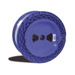
1KM SM Bare Fiber Spool with SC/APC to LC/APC 2m Pigtail at Each End
|


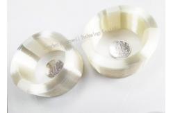


1KM SM Bare Fiber Spool with SC/UPC to LC/APC 2m Pigtail at Each End
In the more common graded index multimode fiber the light rays are also guided down the fiber in multiple pathways. But unlike step index fiber, a graded index core contains many layers of glass, each with a lower index of refraction as you go outward from the axis. The effect of this grading is that the light rays are speeded up in the outer layers, to match those rays going the shorter pathway directly down the axis. Fiber can be identified by the type of paths that the light rays, or modes, travel within the fiber core.
Most OTDRs have an internal ultra physical contact (UPC) spherical polish, but some reflection-sensitive systems use the angled physical contact (APC) polish.
The result is that a graded index fiber equalizes the propagation times of the various modes so that data can be sent over a much longer distance and at higher rates before light pulses start to overlap and become less distinguishable at the receiver end.
There are two basic types of fiber: multimode and single-mode. Multimode fiber cores may be either step index or graded index. Step index multimode fiber derives its name from the sharp step like difference in the refractive index of the core and cladding. For installed spans, linking the OTDR to the span under test requires a hybrid patch cord.
The first method uses a bare-fiber adapter, whichconsists of a plug body that grips the fiber to be
tested. The design of the bare-fiber adapter is such that the fiber can pass completely through the
adapter body and damage the optical port. Because of this, the barefiber adapter must never be
connected directly to the OTDR.Instead, the adapter should be used with a short patch cord and mating
adapter sleeve to isolate damage from the OTDR’s port.
The second method uses a pigtail with a reusable mechanical splice, which allows easy mating of
the fibers to be tested with the OTDR. The Norland reusable mechanical splice has been used for
decades for testing bare fibers.
It features a glass body that internally holds and aligns two fibers.
The splice is filledwith a refractive index matching fluid to reduce reflections.
To make the connection, strip and cleave both of the fibers to be tested,
then insert and center both into the mechanical splice to complete the termination.
|

|
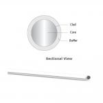
D80 SMA QBH QD HCW400/440/590/880XT22WT 1064nm Bare Fiber Core 400um NA 0.22 980nm Wavelength |
|
OFS CF01493-62 Lightera Optical Fiber MM Step-index, Low OH 0.37 NA 1500/1535 µm |
|
Polarization-Maintaining PM-ESF-7/125 panda-type polarization-maintaining erbium-doped fiber. |
|
30um 50um 70um 0.56NA 0.64NA High numerical aperture (NA) optical fibers |
|
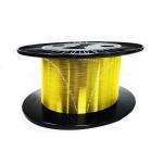
250um to 900um Singlemode Multimode fibers Glass Optical Fiber G652D Single Mode Nude Fiber Optic Cable Raw Materials |
|
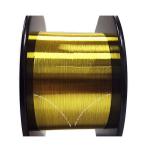
150/165/195um NA 22 100 kpsi Silicone Polyimide High OH Optical Quartz Fiber for Operating Working -65~+350 C |