
Panel for Studying and Testing Distribution Systems (neutral point connection)
|
Detailed Product Description
|
ZE4124 Panel for Studying and Testing Distribution Systems (neutral
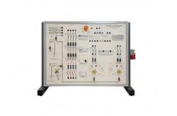
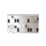
point connection) 1.INTRODUCTION This panel enables teachers to develop an exhaustive class on the state of neutral conductor in distribution systems, so that students can easily learn and test this topic. The actual electric devices assembled in the panel and proper educational terminals with high protection degree against accidental contacts enable to assemble the various confi gurations, as well as a sight check of the operation: tests can be carried out with traditional instruments. 2.PANEL FOR STUDYING AND TESTING DISTRIBUTION SYSTEMS (neutral point connection) Demonstration panel with electric components The fore panel of insulating material is the support of the necessary devices for the development of the training program. The apparatuses are indicated on the panel with standard international symbols. The application fi eld of these devices will cover installations of both civil and business and/or production (handicraft - industrial) sectors. 3.TRAINING PROGRAM: This panel enables to study electric power distribution systems with reference to the following main topics: TT, RN and IT systems Protection against direct contacts Protection against indirect contacts by earthing, electric separation, automatic differential switch Protection against over-currents, selectivity in protection Devices Earthing system and conductors Natural, artifi cial earth plates Checking the insulation resistance in systems insulated from earth (IT) Suitability of materials and of equipment Protections and breaking devices Moreover, it is possible to carry out the following instrumental measurements and checks: Identifi cation of neutral and ground conductors Measurement of insulation resistance Measurement of earth resistance Continuity tests of protection conductors Check of the operation of differential switches Check of the protection with automatic break Measurement of fault loop resistance / impedance Measurement of fi rst earth fault in insulated systems 4.TECHNICAL CHARACTERISTICS: The framework is of chemically treated sheet steel, painted with several coats of epoxy paint. Its base is provided with rubber feet so that it can be positioned on any working top. The panel also includes all the necessary electrical components for a correct power supply of circuits. The main components installed on the panel and accessible via safety terminals for plugs of Ø 4 mm, are: 1 three-phase insulation transformer of 230-400 V / 230-400 V 1500 VA 1 automatic magneto-thermal switch 4 x 6 A, C curve, with minimum-voltage releasing coil, emergency pushbutton with mechanical holding and warning light indicating panel in operation 1 power line of 230 Vac - 1 A for powering auxiliary devices 1 three-pole lever switch for inserting two different values of earth capacitance in IT line 1 simulation of cabin earth with resistance of 0.3 Ω, 1 Ω 1 simulation of earth plate with resistances of 2 Ω, 20 Ω, 200 Ω, 2 kΩ 2 simulators of electric uses with sinusoidal or one-way earth fault current, fault resistance of 50 kΩ, 15 kΩ, 5 kΩ, 1.5 kΩ, 500 Ω, no-resistance earth fault 1 monitor for insulation control in IT systems with regulation of the value of intervention sensitivity and scale for monitoring the instantaneous value of system insulation resistance 1 automatic differential magneto-thermal switch 4 x 2 A, C curve, class AC, possibility of using only the magnetothermal switch without the differential section 1 four-pole differential circuit breaker of 25 A / 0.3 A, class A, “S” selective 1 set of three fuse holders, with breakable neutral conductor and fuses 10.2 x 38 of 1 A and 2 A 1 automatic magnetothermal differential switch 2 x 1 A, curve C, class AC, with possibility of using the only magnetothermal switch without the differential part 1 automatic magnetothermal differential switch 2 x 1 A, curve C, class A, with possibility of using the only magnetothermal switch without the differential part 1 differential relay coupled to a toroidal transformer with adjustable current Idn and intervention time Dimensions of panel: 800 x 600 mm Dimensions of framework: 840 x 450 x 680 mm Net weight: 45 kg 5.REQUIRED UTILITIES (PROVIDED BY THE CUSTOMER) Power supply: 400 Vac 50 Hz three-phase - 1500 VA (Other voltage and frequency on request) OPERATIONAL HANDBOOK WITH EXERCISES ACCESSORIES: Three-phase power cord of 5 m with EEC socket and plug 20 jumpers with safety plugs of Ø 4 mm for assembling various installation conditions Set of 20 various leads with safety plugs of Ø 4 mm |
| Product Tags: building automation training vocational education equipment |
Related Products
|
equipment teaching Building Automation Trainer Equipment Educational Unit for Training on Advanced Electric Devices |
|
450KG Building Automation Trainer 2.0KVA , 2CBM Electrical Trainer Kit |
|
SR3105 Vocational Education Equipment |
|
ZE5109 Vocational Education Equipment / Close Circuit Television Training Workbench |
|
Security And Fire Alarm Systems Technical Teaching Equipment Training Workbench |
|
300W Building Automation Trainer 356kgs , 3.6CBM Telephone Exchange Training |
Email to this supplier