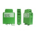
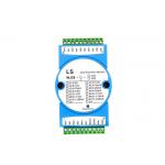
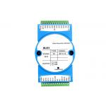
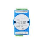
1. General Introduction The LS-TD4015 is an industrial grade standard RTD acquisition
product that supports PT100, PT1000, Cu50, Cu100, Ge53, BA1, BA2,
R5000 and R500 6-channel three-wire RTD inputs. RS485 interface is
optoelectronic isolated. AD acquisition part is also modulus
optoelectronic isolated. It adopts standard MODBUS RTU protocol.
Complaint with industry standards, LS-TD4015 is suitable to use for
a variety of industrial applications and automation systems. It is
convenient to communicate with the host computer and realize a
rapid networking and build your monitoring system. Thermal resistance supports: | PT100 | -200~850℃ | BA1 | -200~650℃ | | PT1000 | -200~850℃s | BA2 | -200~650℃ | | CU50 | -50~150℃ | R5000 | 0~5000Ω | | CU100 | -50~150℃ | R500 | 0~500Ω | | Ge53 | -50~150℃ | | |
2. Parameter | Technique parameter | Description | | Power supply | 9~30V DC | | Input ranges | PT100,PT1000,Cu50,Cu100,Ge53,BA1,BA2,R5000 and R500 | | Excitation current | 250uA | | Advantage | Each channel supports independent configuration (6 channels can be
set separately) | | Input type | 6 channels 3-wire input | | Collect frequency | AD collecting frequency≤10Hz(total rate) | | Resolution | 16 bit | | Accuracy class | ≤ ±0.1%(wiring cable errors not included) | | Input impedance | 20MΩ | | Interface | RS-485 | | Protocol | Default Modbus-RTU,support 8N1, 8O1, 8E1. Data format: SCADA software, PLC, compatible with ADAM-4015+. If you need MODBUS-ASCII or other, please specify when placing
order | | Baud rate | 1200bps, 2400bps, 4800bps, 9600bps, 19200bps, 38400bps, 57600bps,
115200bps | | Distance | RS485 distance<1000m, can use repeater | | Stability | Use high quality chips inside, built-in dual watchdog, reliable and
stable operation | | Protection level | Power Pin polarity protection, input Pin photoelectric isolation,
AD input Pin and communication port ±15KV ESD protection, isolation
voltage 2500Vrms, 500DC continuous, lightning protection, surge
protection | | Power consumption | <2000mW | | Weight | 0.3kg | | Mounting way | Standard 35mm U-shaped Din rail installation |
3. Pin Definition | Pin No. | Pin name | Description | | 1 | COM4 | Ch 4 COM port | | 2 | RTD4- | RTD input ch4- | | 3 | RTD4+ | RTD input ch4+ | | 4 | COM5 | Ch 5 COM port | | 5 | RTD5- | RTD input ch5- | | 6 | RTD5+ | RTD input ch5+ | | 7 | NC | NC | | 8 | NC | NC | | 9 | NC | NC | | 10 | DATA+ | RS-485 A | | 11 | DATA- | RS-485 B | | 12 | +VS | Power supply +(9~30V) | | 13 | GND | Power supply -(ground of power) | | 14 | RTD0+ | RTD input ch0 + | | 15 | RTD0- | RTD input ch0 - | | 16 | COM0 | Ch0 Com port | | 17 | RTD1+ | RTD input ch1+ | | 18 | RTD1- | RTD input ch1- | | 19 | COM1 | Ch1 Com port | | 20 | RTD2+ | RTD input ch2+ | | 21 | RTD2- | RTD input ch2- | | 22 | COM2 | Ch2 Com port | | 23 | RTD3+ | RTD input ch3+ | | 24 | RTD3- | RTD input ch3- | | 25 | COM3 | Ch3 Com port | | 26 | GND | GND |
|
