
14400 High Resolution Rotary Encoder , Stepper Motor Rotary Encoder IP40
|
|
14400 high resolution servo motor rotary encoder line driver IC-HD7 output KN35 DC8-30V
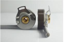
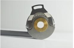
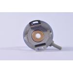
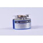
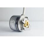
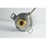
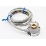
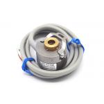
Key Feather of KN35 encoder Brand: HENGXIANG External diameter: 35mm Thickness: 18mm Installation dimension: R13.5mm, R14.5mm, R20mm Hollow shaft type: blind hole; through hole, taper hole Supply voltage: DC5V ; DC8--30V Sock(endure): 490m/s2 ,11 ms three times for X,Y,Z direction individually Shell Material: die cast aluminum Certification: CE
Parameter table for KN35 incremental encoder
Encoder Operation method With proper connections you can use the Push Pull interface to replace true open collector circuits by using an external diode connected in a way to limit the direction of the current for RS422 (TTL) circuits provide a constant 5 V signal level that is not dependent on the supply voltage. Two supply voltage ranges can be selected: From 4.75 to 5.5 VDC (can be used to replace open collector output drivers) or from 8 to 30 VDC. Using differential signals the output fully complies to the RS422 standard. The differential outputs have the highest frequency response capability and the best noise immunity. To ensure this the receiver should also be a differential. Replacement of Older Output Drivers A logic gate interprets certain input voltages as high (logic 1) or low (logic 0). TTL (transistor-transistor-logic): A signal above 2 V is interpreted as logic 1 and a signal less than 0.8 V is interpreted as logic 0. The output voltage ranges between 0-5 V. HTL (high-threshold-logic): A signal above 3 V is a logic 1 and a signal less than 1 V is a logic 0. The high output signal level is dependent from the supply voltage. Because of the higher voltage difference between logic 0 and 1, the HTL logic is more immune to interference and more resistant against electrical noise.
Mechanical degree is the actual rotation of the shaft in degrees. Electrical degree is used for electrical signals. The required time for completing one alternating voltage/current cycle is defined as 360 electrical degrees (el°). For incremental encoders, one cycle is equal to one complete pulse. With a given PPR the electrical degree can be converted to mechanical degree for any incremental encoder.
|
||||||||||||||||||||||||||||||||||||||||||||||||||||||||||||||||
| Product Tags: optical motor shaft encoders cnc rotary encoder |
|
Through Hole 48mm Dc Motor Shaft Encoder K48 OIH48 - TS5214N510 Replacement |
|
Mini Servo Motor Encoder ABZUVW Phase OIH48 - 1024P6L65v Encoder K48 |
|
Outer Diameter 35mm Dc Motor Shaft Encoder Line Driver Output With Delay Signal 5V DC |
|
Blind Hole 6mm K35 Miniature Rotary Encoder 2500 Resolution 4 Poles |
|
DC8-30V Servo Motor Rotary Encoder KN35 Thickness 18mm With Mounting Spring Plate |
|
Hole Shaft Dc Motor With Encoder KN35 / Small Volume Industrial Rotary Encoder |