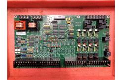
The DS200DDTBG2ABB is an LCI Auxiliary I/O Terminal Board. This PCB was created as a component for the Mark V system from GE.
The Mark V was the second of the Speedtronic gas and steam turbine
management systems to offer triple redundant back-ups on critical
controls and protection parameters. This DS200DDTBG2ABB board's
Mark V product series also includes features such as built-in
diagnostics, online maintenance, and a direct sensor interface. The DS200DDTBG2ABB PCB featured on this personalized product page
is actually not the original LCI Auxiliary I/O Terminal Board
manufactured for placement in the larger Mark V Turbine Control
System Series; that would be the DS200DDTBG2 parent printed circuit
board missing all three of this DS200DDTBG2ABB product's
significant product revisions.
Hardware Tips and Specifications
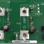
The DS200DDTBG2ABB is a high voltage board. Its function is to
create system connections for auxiliary I/O signals. Given this specific intended Mark V Turbine Control System Series
functionality, it should come as no true surprise that this
DS200DDTBG2ABB product offering makes use of its own elevated
series of functionality-encouraging hardware components and
component specifications. The DS200DDTBG2ABB board receives power from and is connected to
the DS200ADMA board, which is a daughterboard module located on the
DS200DSPC digital signal processor control board.The DS200DDTBG2ABB is built with multiple inputs and outputs. These
outputs include high voltage AC inputs (2,) high current signal
inputs (6,) low current signal inputs (3,) 4-20 mA current loop
inputs (up to 2,) and undedicated voltage inputs. The current loop inputs in this DS200DDTBG2ABB LCI Auxiliary I/O
Terminal Board's assembly are reassigned from the CT or LEM input
channels using jumpers. The DS200DDTBG2ABB board featured here also
has four buffered analog outputs and two 4-20mA current outputs.
The board also has sixteen digital Input/Outputs.
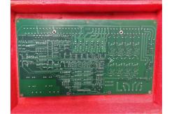
The DS200DDTBG2ABB PCB is built with 33 TP test points, used for
signal measurement, as well as 17 LEDs (DS1-DS17.) The board
includes twelve jumper switches with 3 positions each. The factory setting for these switches is on the 1-2 position. In
terms of standard voltage-limiting hardware components, the
DS200DDTBG2ABB LCI Auxiliary I/O Terminal Board makes use of two
transformers, four relays, and fourteen transistors. The
DS200DDTBG2ABB uses capacitors and resistors as well, and features
an assembly secured by the normal style of PCB coating that it has
been chemically-treated by. This DS200DDTBG2ABB Mark V Series product's internal assembly also
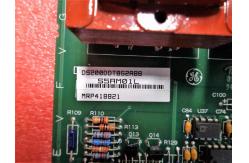
has eight varistors and fifteen resistor network arrays. Finally, this DS200DDTBG2ABB printed circuit board has five
terminal strips that vary from three screw positions to thirty-six
screw positions, and has many integrated circuits, including a chip
with board identification and hardware revision information. More information on the board functions, application data,
features, and installation can be found in GEI-100219, a
publication from General Electric that may be hard to retrieve
through the internet given this DS200DDTBG2ABB product's series as
a Mark V legacy series product offering. Before making a final purchase decision on this DS200DDTBG2ABB
high-voltage LCI Auxiliary I/O Terminal Board, it is crucial to
realize that its originally-introduced performance specifications
and dimensions have been impacted through its inclusion of a full
product revision table with two functional product revisions and an
artwork configuration revision.