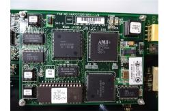
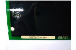
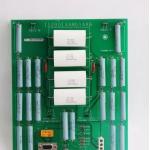
DS200DDTBG1A is an LCI Auxiliary I/O Terminal Board manufactured
and designed by General Electric as part of the Mark V Series used
in GE Speedtronic Control Systems. The DS200DDTB board (DDTB) is a
high-voltage terminal board for system connections of auxiliary I/O
signals. The board connects to a DS200ADMA (ADMA) analog-to-digital
module daughterboard that is mounted on a DS200DSPC (DSPC) digital
signal processor control board. High-density connectors and a
ribbon cable connect the DDTB to the ADMA board. Power for the DDTB
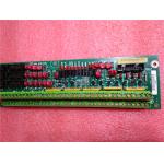
is provided by the ADMA board. The DDTB provides signal
conditioning, scaling, buffering, and isolation to make the harsh
environment system-level signals accessible to the DSPC board’s
digital signal processor (DSP). External wiring connections from
high voltage signals, contact I/O, current measurement (via
low-level Hall-effect devices), or high-current CTs can be
connected to the DDTB terminals. There are G1 and G2 versions of
the DDTB board. The G2 lacks some of the functionality of the G1
and is noted where applicable.
FEATURES:
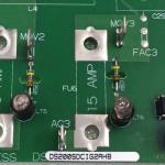
HIGH VOLTAGE AC INPUTS: There are two isolated inputs for connection to high voltage AC
signals. These use a step-down transformer, passive filtering, and
a buffer to provide a ±5 V peak-to-peak signal to the ADMA board’s
VCO inputs (at 693 V rms applied). These inputs have a separate
screw terminal block rated and isolated for 1000 V peak transients.
HIGH CURRENT SIGNAL INPUTS: There are six inputs with current sensing resistors suitable for
±5 amp continuous current signals (intended for CT inputs). These
are buffered differentially and can tolerate ±12 V of common mode
voltage. Each input is filtered and scaled. These inputs have a
screw-type terminal block and are protected from voltage surges.
LOW CURRENT SIGNAL INPUTS: There are three inputs with current sensing resistors suitable for
±0.224 amp continuous current signals (intended for LEM current
transducer signals). These are buffered differentially and can
tolerate ±12 V of common mode voltage. Each input is filtered and
scaled. These inputs have a screw-type terminal block and are
protected from voltage surges.
4-20 mA CURRENT LOOP INPUTS: There are provisions for reassigning two of either the CT or LEM
input channels as receivers for 4-20 mA current loop input signals.
This alternate assignment is made by resetting certain jumpers. The
input resistance is 192 ohms and the analog input is offset so that
0 mA yields negative full scale and 20 mA yields positive full
scale. Open loop detection and input normalization are managed by
software.
UNDEDICATED VOLTAGE INPUTS: A differential input voltage amplifier is provided for feeding an
analog VCO input on the ADMA board. The gain of this amplifier is
1/2 allowing a ±10 V input signal range. These inputs have a
screw-type terminal block and are protected from voltage surges.
4-20 mA CURRENT OUTPUTS: Two of the analog outputs also drive current source output buffers
to provide support for the 4-20 mA current loop output signals.
Both the voltage and current outputs are active at all times and
can be used individually or together by wiring to their respective
output terminals. There is an inversion and gain stage in the 4-20
mA driver such that a +5 V input from the ADMA board causes the
output to produce 4 mA and a −5 V input causes the output to
produce 20 mA. An output is not permitted to produce 0 mA to avoid
confusion with open loop detection.
WOC has the largest stock of GE Speedtronic Control System Replacement Parts. We can also repair your faulty boards. WORLD OF CONTROLS can also
supply unused and rebuilt backed-up with a warranty. Our team of
experts is available round the clock to support your OEM needs. Our
team of experts at WOC is happy to assist you with any of your automation requirements.
For pricing and availability on any parts and repairs, kindly get
in touch with our team by phone or email.