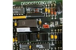
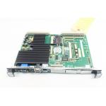
The GE I/O TC2000 Analog Board DS200TCCBG1BED features one 80196
microprocessor and multiple PROM modules. It also contains one LED
and 2 50-pin connectors. The LED is visible from the side view of
the board. The IDs for the 50-pin connectors are JCC and JDD. The
microprocessor uses the processing instructions and firmware on the
PROM modules. Further programming or firmware updates are not
necessary when you install the replacement board. All that is
necessary is to move the PROM modules from the old board to the
sockets on the replacement board. In that way, you can resume drive
activity and know that processing will be the same.
You must also reconnect the ribbon cables into the same connectors
on the replacement board. This applies to both the 50-pin ribbon
cables and also the 34-pin ribbon cables. Because there are 5
34-pin connectors, there is a chance that you might connect the
ribbon cables into the wrong connectors. There is also a chance of
connecting the 50-pin connectors into the wrong connectors. All the
connectors have connector IDs and even if the replacement board is
a newer version, the connector IDs will be the same.
You might find that the components on the replacement board are in
different locations and that the components look different. Due to
extensive product testing, compatibility between the versions is
maintained and the replacement board will provide the same
processing results as the defective board. Plug the ribbon cables
into the same connectors on the new board and use the connector IDs
to map the old board to the new board.
The General Electric I/O TC2000 Analog Board DS200TCCBG1B features
one 80196 microprocessor and multiple PROM modules. It also
contains one LED and 2 50-pin connectors. The LED is visible from
the side view of the board. The IDs for the 50-pin connectors are
JCC and JDD. The board is also populated with 3 jumpers. The
jumpers have IDs printed on the surface of the board. The IDs are
JP1, JP2, and JP3.
When the original board is installed in the drive, the installer
configures the board to best meet the requirements of the drive.
The jumpers enable the installer to set the configuration values by
changing the position of the jumpers. The default positions of the
jumpers are used under most conditions and require no further
action by the installer. However, in some situations the installer
changes the position of the jumper based on the information
available in the printed information provided with the board.
In a 3-pin jumper, the jumper covers 2 pins at a time. For example,
the jumper might cover pins 1 and 2 or pins 2 and 3. To move a
jumper, grasp the jumper with your thumb and forefinger and pull it
off the pins. Then, align the jumper with the new pins and slide it
into position. Some jumpers are not used for configuring the board
and have only one supported position. In this case the alternate
position is used for product testing by the manufacturer to test a
particular circuit or function.